

1-10PCS TLP281-4 4-Channel Optocoupler Isolation Module High/Low Level Input for Arduino, Raspberry Pi, Industrial Control
5PCS
$21.47
Sale price
$21.47
Regular price
$0.00
Skip to product information


1-10PCS TLP281-4 4-Channel Optocoupler Isolation Module High/Low Level Input for Arduino, Raspberry Pi, Industrial Control
$21.47
Sale price
$21.47
Regular price
$0.00
Description
SPECIFICATIONS
Application: other
Brand Name: SZYTF
Choice: yes
Condition: New
Dissipation Power: n/a
High-concerned chemical: none
Operating Temperature: n/a
Origin: Mainland China
Supply Voltage: n/a
Type: other
is_customized: Yes
semi_Choice: yes
Product Description:
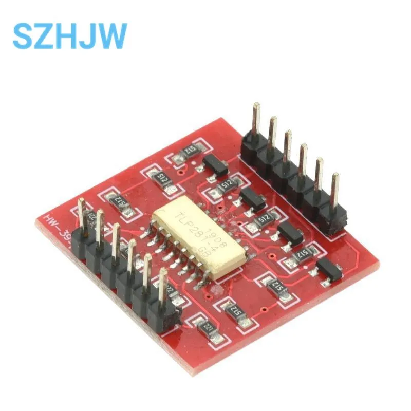
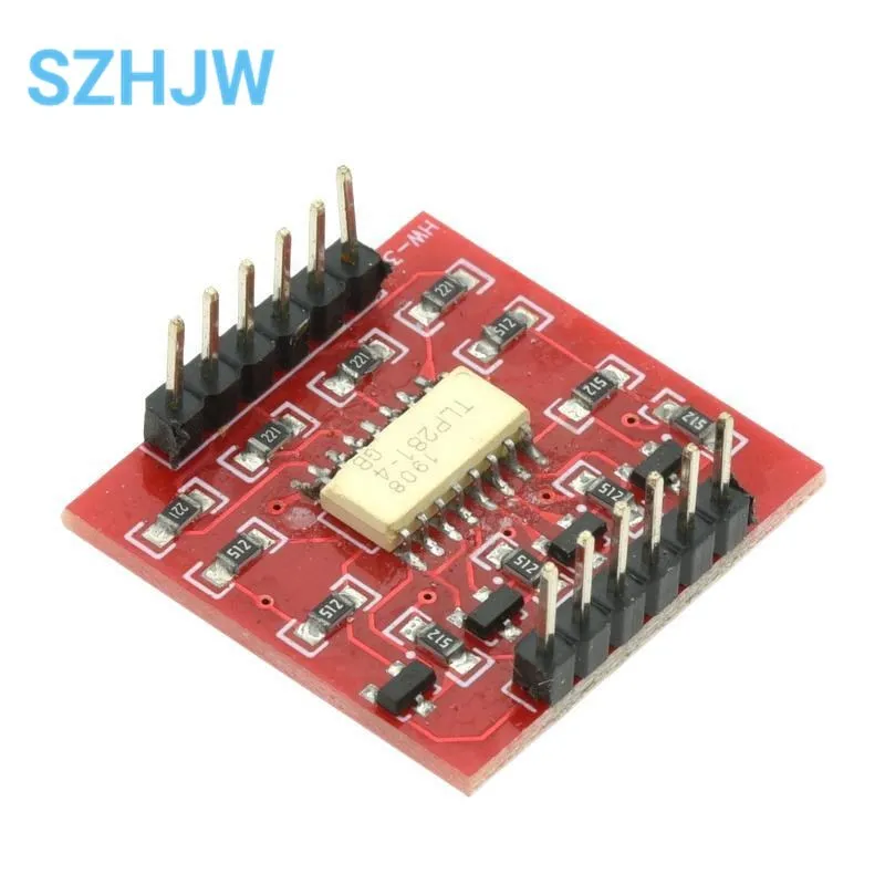
This board is helpful for connecting digital systems (like a 5V microcontroller) to a high-voltage or noisy system. This board electrically isolates a controller from the high-power system by use of an opto-isolator IC.
This IC has four LEDs and four photodiodes built-in.
This allows the low-voltage side to control a high voltage side
We often use this board to allow a microcontroller control servos
or other motors that use a higher voltage than the TTL logic on the (3.3V or 5V) micro,
and may cause electromagnetic interferance with our system as the motors turn on and off.
This board will isolate the systems, creating a type of electrical noise barrier between devices
This breakout board uses the TLP281 optoisolator and discrete transistors to correct the logic.
Function:
1. Use low level to control high level. For example, 3V or 5V voltage of MCU is used to control 9V or 12v voltage.
2. The HVCC should not exceed 24V. Output OUT1/OUT2/OUT3/OUT4 Output current equal to HVCC/5.1K, absorption current 500ma.
3. This module adopts Toshiba TLP281 chip.
Schematic diagram:
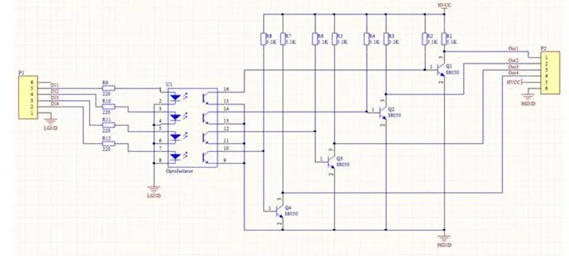
Input/output instructions:
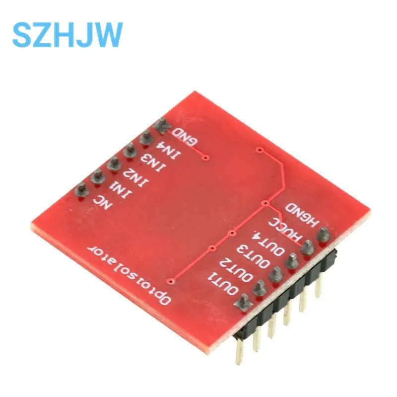
Input terminal: IN1/IN2/IN3/IN4, connected to the single chip microcomputer or the IO port of Arduino, GND connected to the single chip microcomputer or the GND of the Arduino development board. IN1/IN2/IN3/IN4 respectively controls OUT1/OUT2/OUT3/OUT4.
Output: OUT1/OUT2/OUT3/OUT4
Output end: HVCC: connects to the controlled high voltage positive terminal, HGND connects to the controlled high voltage negative terminal
Use: When IN1 is high, the corresponding OUT1 voltage is equal to HVCC, when IN1 is low, the corresponding OUT1 voltage is equal to HGND
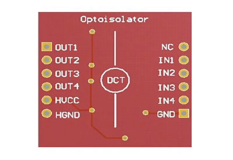
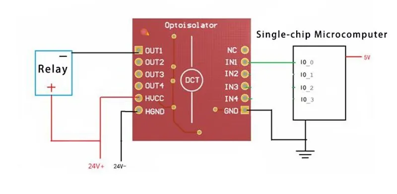
Use example:
The following example shows how to control the rotation of a 24V motor using the IO port of a single chip computer. In the figure, the working voltage of the motor is 24V. The red "+" represents the positive power terminal of the motor, and the black "-" represents the negative power terminal of the motor. When the IO_0 port of the microcontroller outputs high voltage, the motor rotates; when the IO_0 port outputs low voltage, the motor stops rotating.
Free Shipping Over $199
- Standard Shipping: Standard Shipping (12–18 Business Days)
- Express Shipping: Expedited Shipping (5–9 Business Days)
- Free Shipping: Orders over $199 qualify automatically
- Tracking: Full tracking number provided for all orders
30-Day Return Policy
- Returns: 30-day hassle-free return window
- Condition: Items must be unused and in original packaging
- Refund: Full refund processed within 3-5 business days
Why Choose Us?
- Factory Direct: ISO/TS 16949 certified manufacturer
- Quality: 100% electrical continuity tested before shipment
- Experience: 15+ years in automotive connector industry
- Support: Professional technical support available

You may also like
Blog posts
Title
An excerpt of your blog post's content
Title
Date|Author
Subscribe to our emails
Be the first to know about new collections and special offers.