

1/3/5/10PCS LDR Photoresistor Sensor Module Light Intensity Detection Brightness Light Sensor for Arduino LM393
1PCS
$7.79
Sale price
$7.79
Regular price
$0.00
Skip to product information


1/3/5/10PCS LDR Photoresistor Sensor Module Light Intensity Detection Brightness Light Sensor for Arduino LM393
$7.79
Sale price
$7.79
Regular price
$0.00
Description
SPECIFICATIONS
Brand Name: XYCJJCXL
Choice: yes
High-concerned chemical: none
Material: Polymer
Origin: Mainland China
Output: Analog Sensor
Theory: Resistance Sensor
Type: Humidity Sensor
Use: Temperature Sensor
semi_Choice: yes
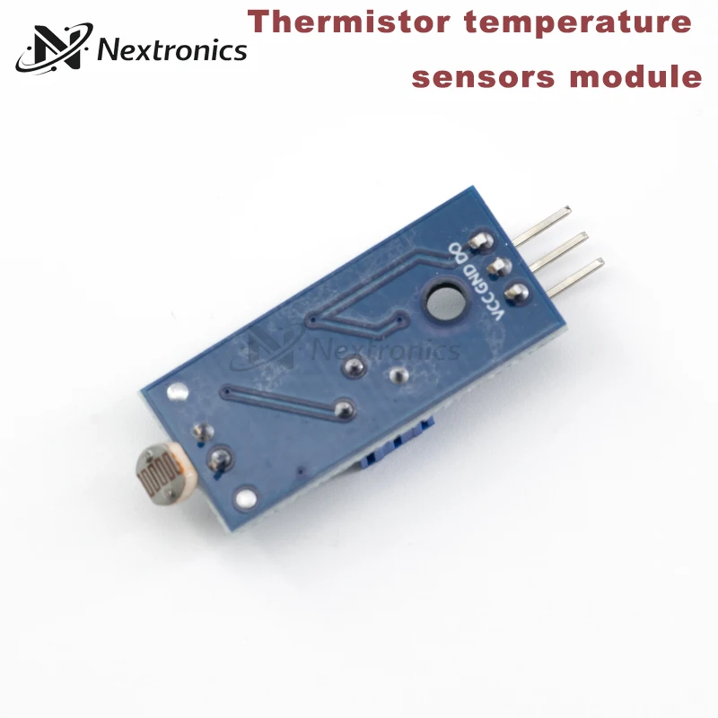
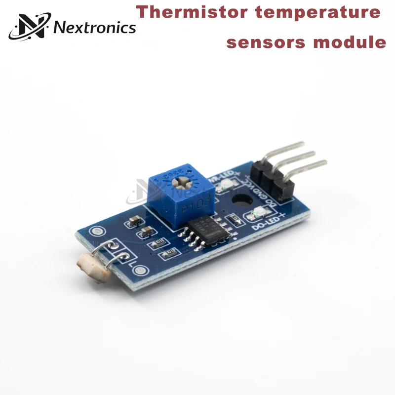
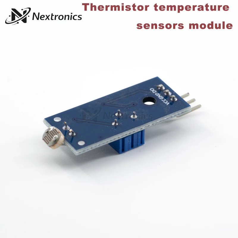
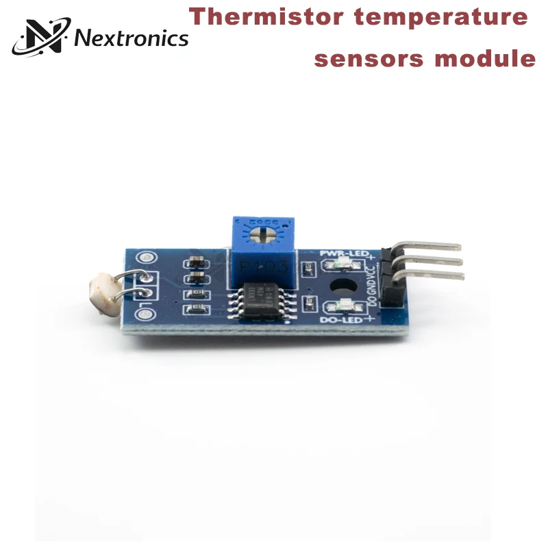
Photoresistor Sensor Module
The Principle of Photoresistance
Photoresistors are special resistors made of semiconductor materials such as vulcanized or selenized barriers,
and their working principle is based on the internal photoelectric effect.
With the increase of light intensity, the resistance value decreases rapidly.
Because the carriers generated by light are involved in conduction, they drift under the action of applied electric field,
and the electrons rush to the positive terminal of the power supply and the holes rush to the negative terminal of the power supply,
so that the resistance value of the photoresistor decreases rapidly.
In the absence of light, it is almost in a high resistance state, and the dark resistance is very large.
Module Parameter
Working voltage: DC 3.3V-5V
Output type: TTL Digital Signal (DO) / Analog Signal (AO)
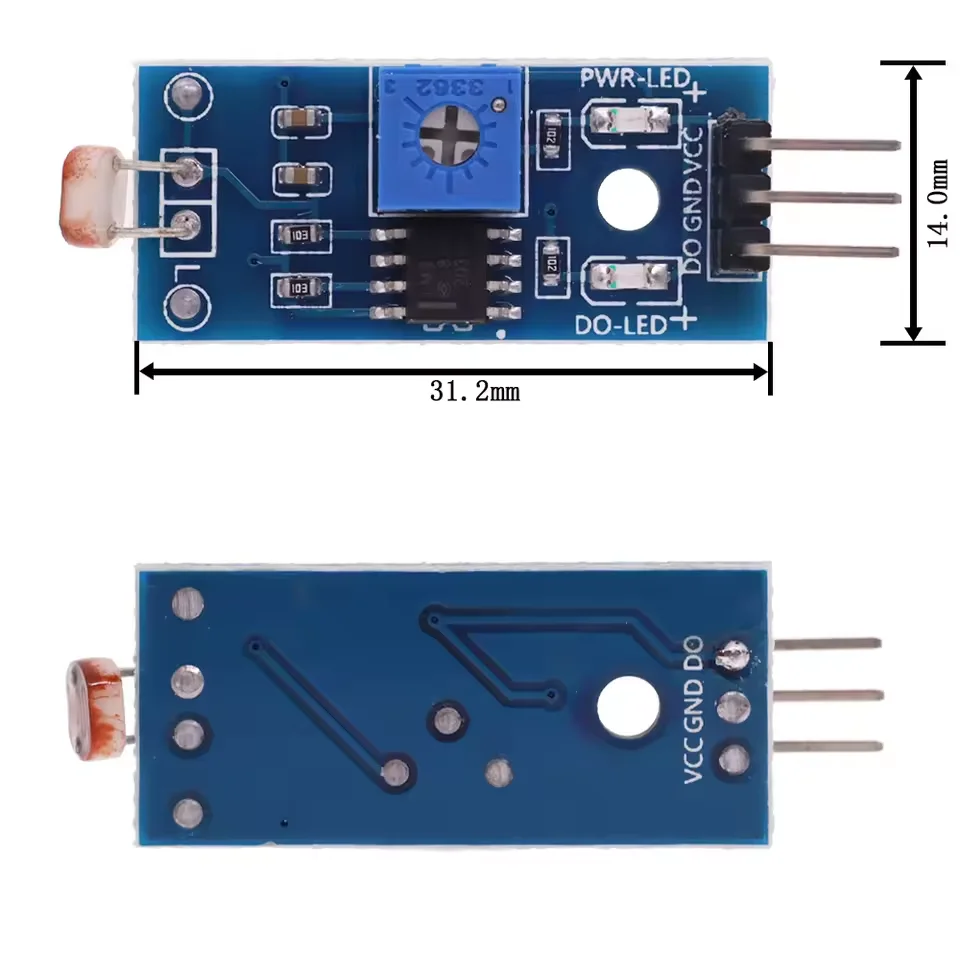
Module pin: 4 pins
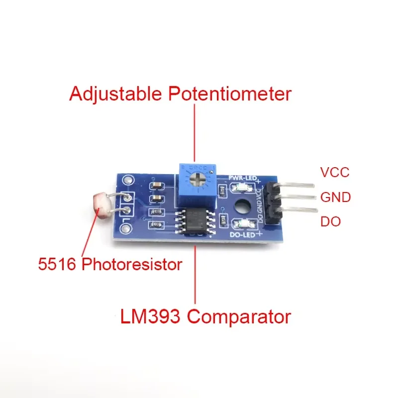
Photoresistor Model: 5516
Module PCB size: 3.2 × 1.4cm
Module Feature
1. A sensitive photoresistor sensor is used
2. Comparator output, the signal is clean, the waveform is good, the driving ability is strong, more than 15mA
3. Equipped with adjustable potentiometer, can adjust the detection light brightness
4. Working voltage: 3.3V-5V
5. Output form: DO digital switching output and AO analog voltage output
6. Fixed bolt holes are provided for easy installation
7. Small board PCB size: 3.2cm × 1.4cm
8. Use a wide-voltage LM393 comparator
Module Usage Instructions
1. The photoresistor module is sensitive to environmental light and is generally used to detect the brightness of ambient light, trigger the MCU or relay module.
2. When the ambient light brightness does not reach the set threshold, the DO end outputs a high level. When the ambient light brightness exceeds the set threshold, the DO end outputs a low level.
3. The DO output can be directly connected with the MCU. Through the MCU, it can detect the high and low levels to detect the change of environmental light brightness.
4. The DO output can directly drive the relay module, which can form a light control switch.
5. The small board analog output AO can be connected to the AD module. Through AD conversion, you can get a more accurate value of the ambient light intensity.
6. Pay attention to the positive and negative terminals of the power supply. Do not connect them in reverse, otherwise it may burn the chip.
7. Switch signal indicator light: output low level, light on; output high level, light off. The specific voltage is related to the power supply voltage.
8. Threshold setting method: put the module in a bright environment or the threshold light environment that needs to be set, adjust the potentiometer so that the DO output indicator is just not bright, and the sensitivity is the highest at this time.
Free Shipping Over $199
- Standard Shipping: Standard Shipping (12–18 Business Days)
- Express Shipping: Expedited Shipping (5–9 Business Days)
- Free Shipping: Orders over $199 qualify automatically
- Tracking: Full tracking number provided for all orders
30-Day Return Policy
- Returns: 30-day hassle-free return window
- Condition: Items must be unused and in original packaging
- Refund: Full refund processed within 3-5 business days
Why Choose Us?
- Factory Direct: ISO/TS 16949 certified manufacturer
- Quality: 100% electrical continuity tested before shipment
- Experience: 15+ years in automotive connector industry
- Support: Professional technical support available

You may also like
Blog posts
Title
An excerpt of your blog post's content
Title
Date|Author
Subscribe to our emails
Be the first to know about new collections and special offers.