Product Highlights
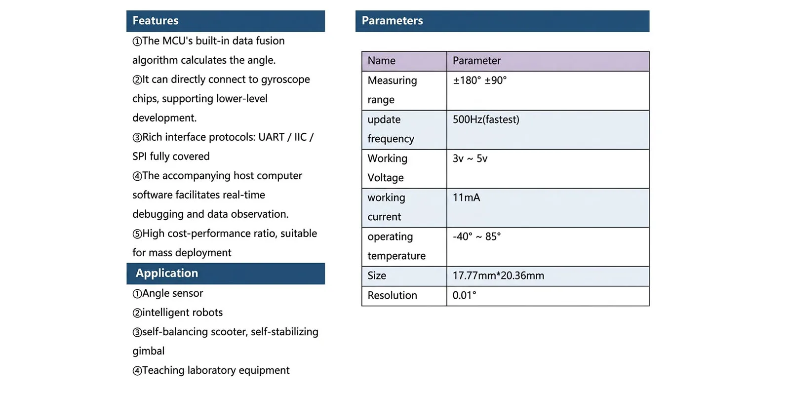
1. The MCU uses a built-in data fusion algorithm to calculate angles.
2. Can be directly connected to gyroscope chips, supporting low-level development.
3. Rich interface protocols: UART/IIC/SPI fully covered
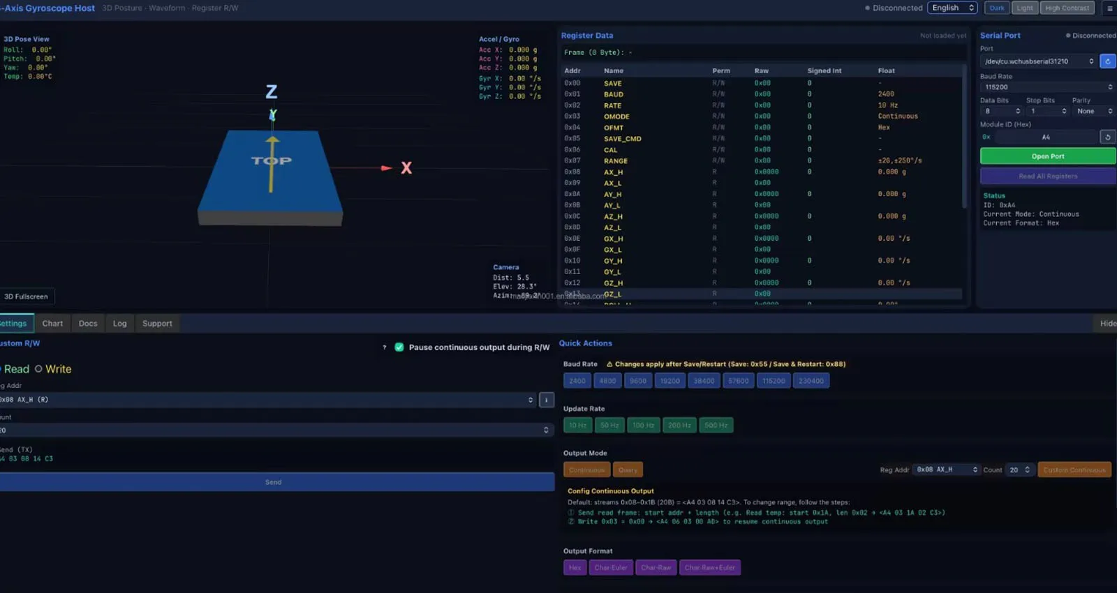
4. It comes with host computer software for convenient real-time debugging and data observation.
5. High cost-performance ratio, suitable for batch deployment.
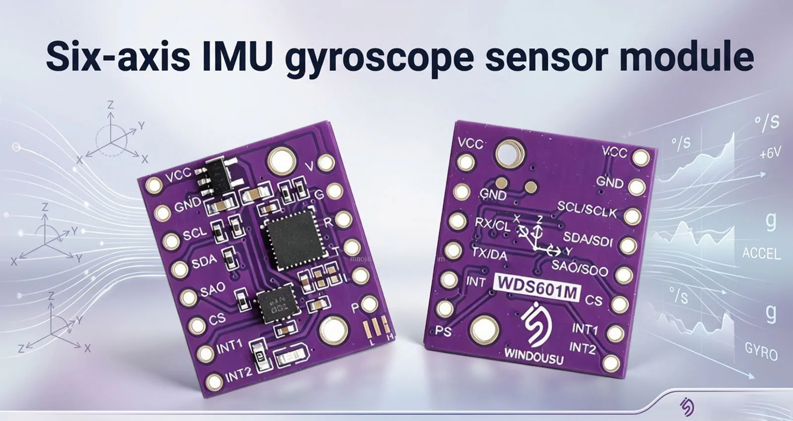 The WDS601M is a low-cost six-axis gyroscope module with advantages such as small size, low power consumption, easy installation, and rich interface protocols. This module supports two operating modes and four communication methods, allowing users to flexibly choose according to their needs.
• Onboard MCU Mode: Supports UART and IIC communication protocols. After reading data from the gyroscope chip, the MCU calculates the angle data using a built-in data fusion algorithm, facilitating direct secondary development by users. Supports range configuration (power-off saving), configurable module addresses, and allows multiple modules to be installed on the same bus. • Gyroscope Chip Mode: The gyroscope chip supports IIC and SPI communication protocols. Users can communicate directly with the gyroscope chip according to the chip datasheet to achieve richer functionality.
This module supports tilt warning (switch output). A tilt threshold can be set, and the INT pin outputs a low level when the roll angle exceeds the set range.
Precautions:
* IIC/SPI communication is a built-in pin interface of the chip. * The UART interface outputs data from the sensor after processing by the MCU algorithm, including direct angle data. * Arduino test code and host computer software debugging are provided.fatkun
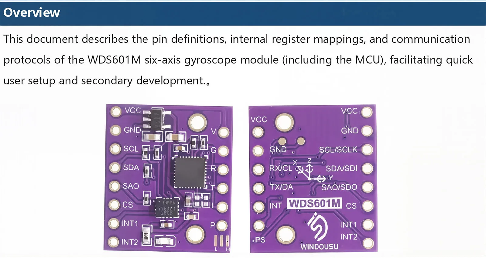
 Pin Description Module Coordinate System: Right-handed coordinate system.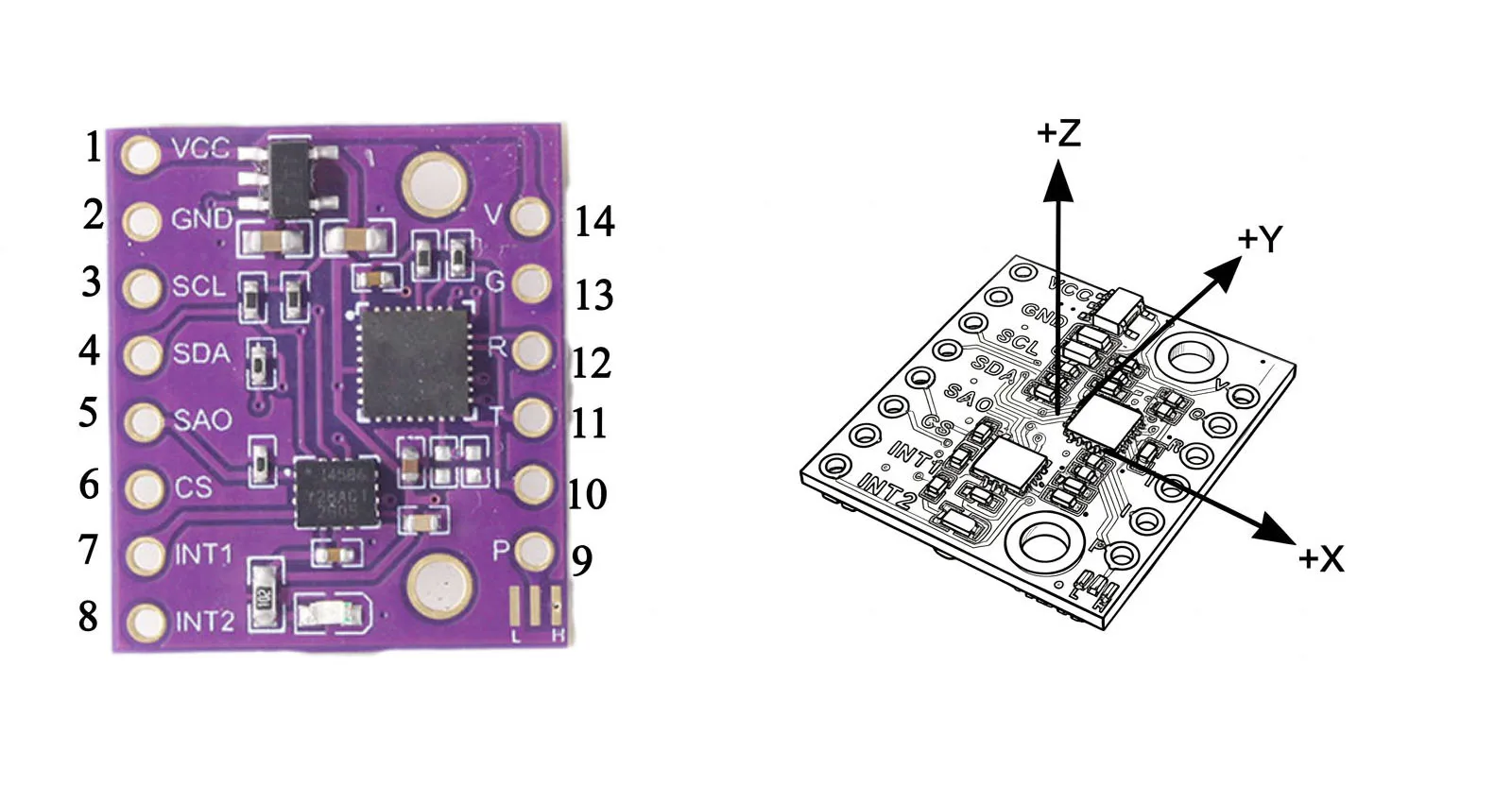
password |
Pin Name |
describe |
Pin 1 |
Voltage VCC |
Positive power supply (3–5 volts) |
pin 2 |
Grounding |
negative terminal of power supply |
3 pins |
SCL/Clock |
Chip IIC interface SCL/Chip SPI interface SCLK |
pin 4 |
SDA/SDI |
Chip IIC interface SDA / Chip SPI interface SDIO |
5 pins |
SA0/SD0 |
Chip IIC interface SA0 / Chip SPI interface SDO |
6 pins |
customer service |
Chip SPI interface CS |
7 pins |
International 1 |
Chip interrupt pin 1 |
8 pins |
International 2 |
Chip interrupt pin 2 |
9 pins |
Notes |
Mode selection: Gyroscope chip output / MCU serial port mode / MCU IIC mode |
10 pins |
internationality |
In serial port mode, a tilt warning is triggered; in IIC mode, a data ready interrupt is triggered. |
11 pins |
Transmit/Receive |
UART_TX/ IIC_SDA |
12 pins |
RX/SEAT |
UART_Receive/IIC_Clock |
13 pins |
GND |
negative terminal of power supply |
14 pins |
VCC |
Positive power supply (3–5 V) |
Please note:
The operating mode can be selected via the PS pin or the solder joint at the bottom right of the module.
① PS pin floating: This module is an independent gyroscope chip and requires manual startup and configuration; it supports both IIC and SPI operating modes.
② PS pin connected to VCC: MCU serial port mode.
③ PS pin connected to GND: MCU IIC mode.
Host Software
The accompanying host computer software can display attitude angles, configure register parameters, and perform real-time calibration, facilitating debugging and data observation.
For detailed instructions, please refer to the software's built-in help documentation