

8 Digit Bit MAX7219 Digital Tube Display Module Board 7 Segment Digital LED Display for 3.3V 5V STC51/AVR/STM32
Red Board
$13.64
Sale price
$13.64
Regular price
$0.00
Skip to product information


8 Digit Bit MAX7219 Digital Tube Display Module Board 7 Segment Digital LED Display for 3.3V 5V STC51/AVR/STM32
$13.64
Sale price
$13.64
Regular price
$0.00
Description
SPECIFICATIONS
Application: Computer
Brand Name: diymore
Choice: yes
Condition: New
Dissipation Power: 7 Segment Digital LED Display
High-concerned chemical: none
Operating Temperature: 7 Segment Digital LED Display
Origin: Mainland China
Supply Voltage: 3.3V 5V
Type: Voltage Regulator
is_customized: Yes
semi_Choice: yes
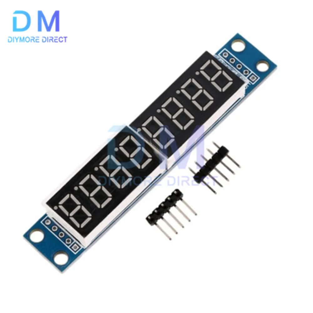
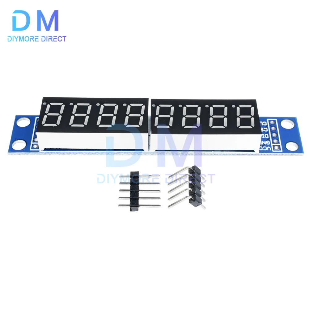
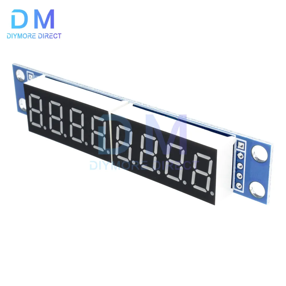
Blue board:
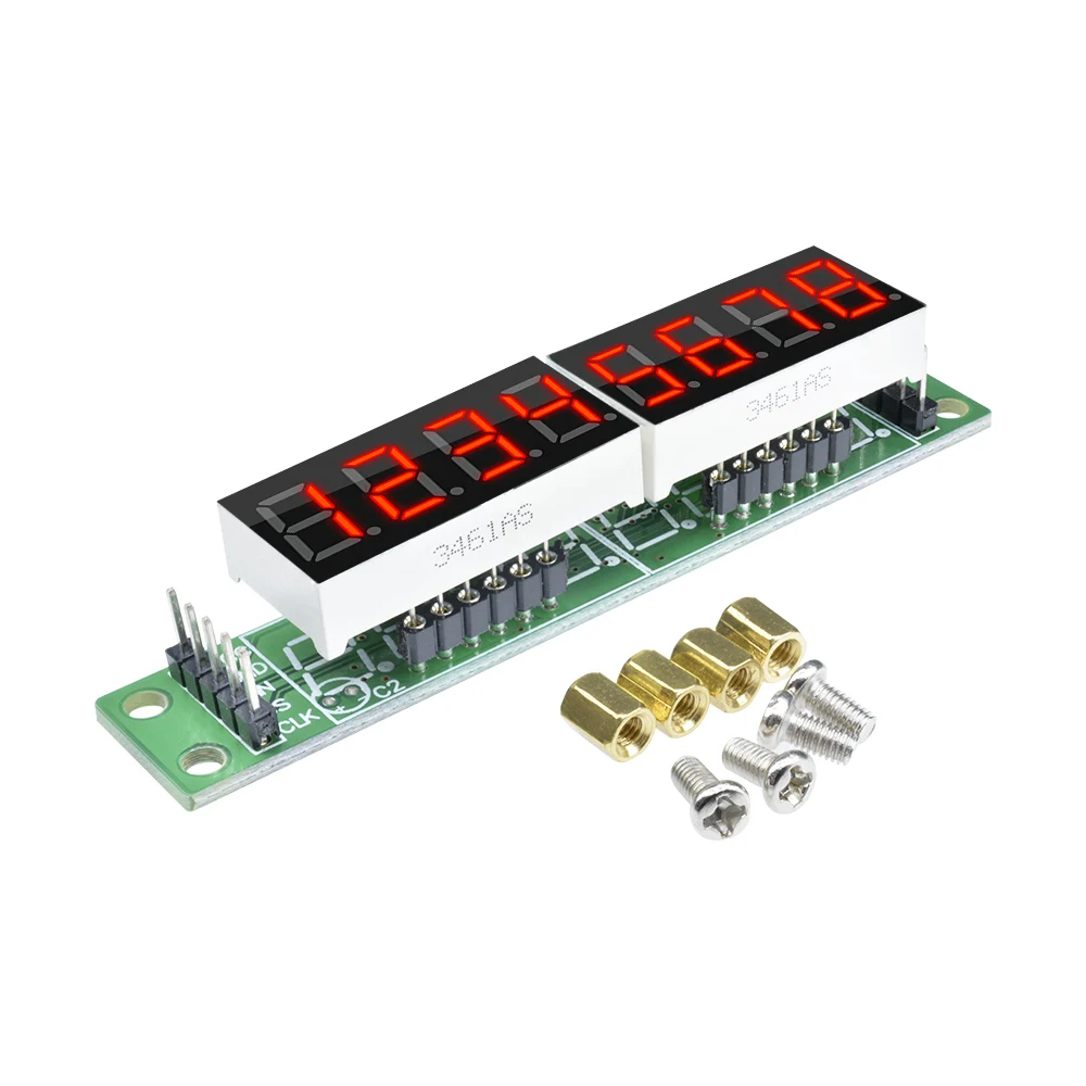
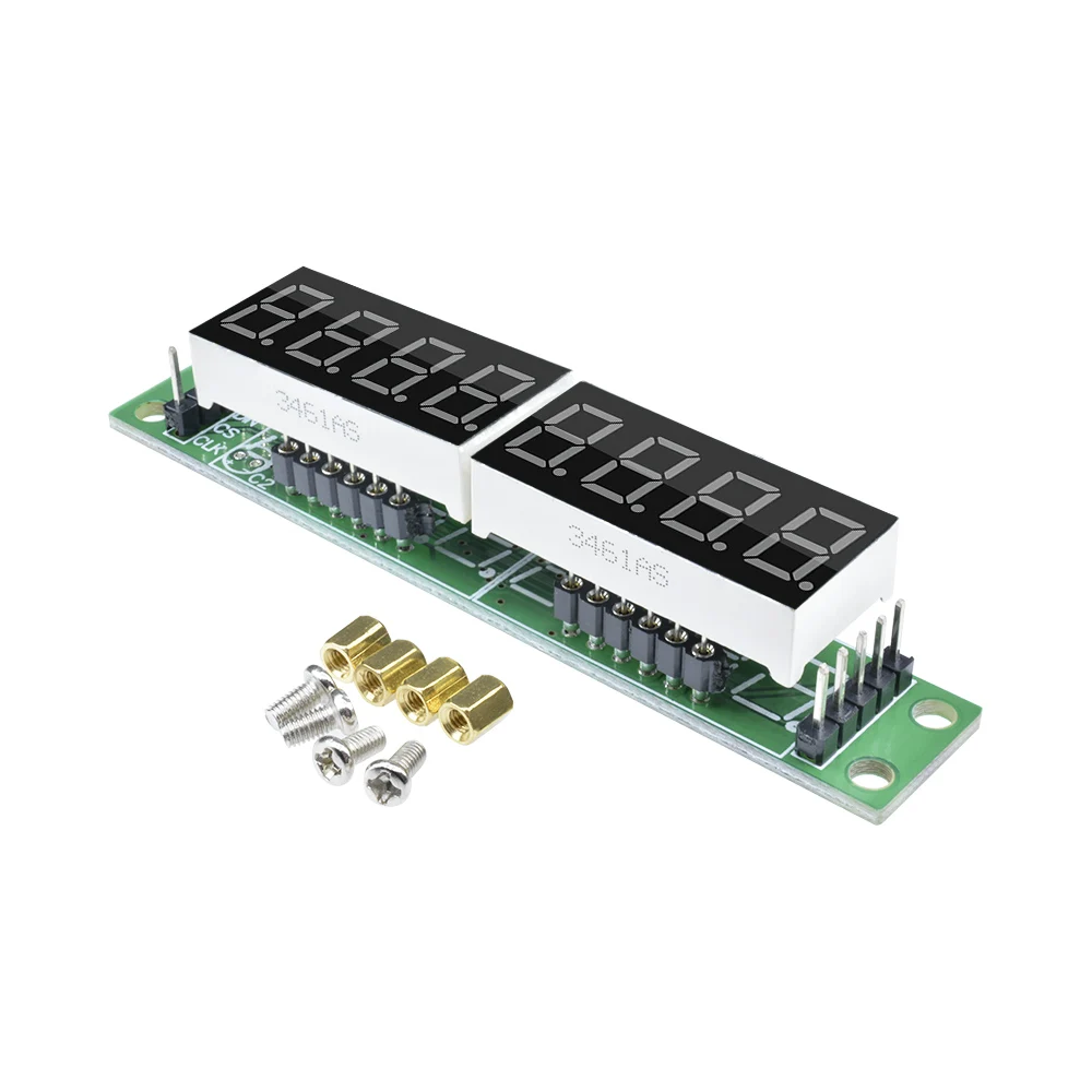
1. The MAX7219 drive is displayed
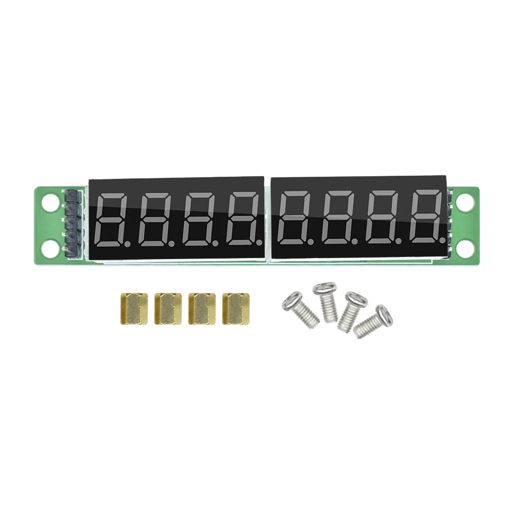
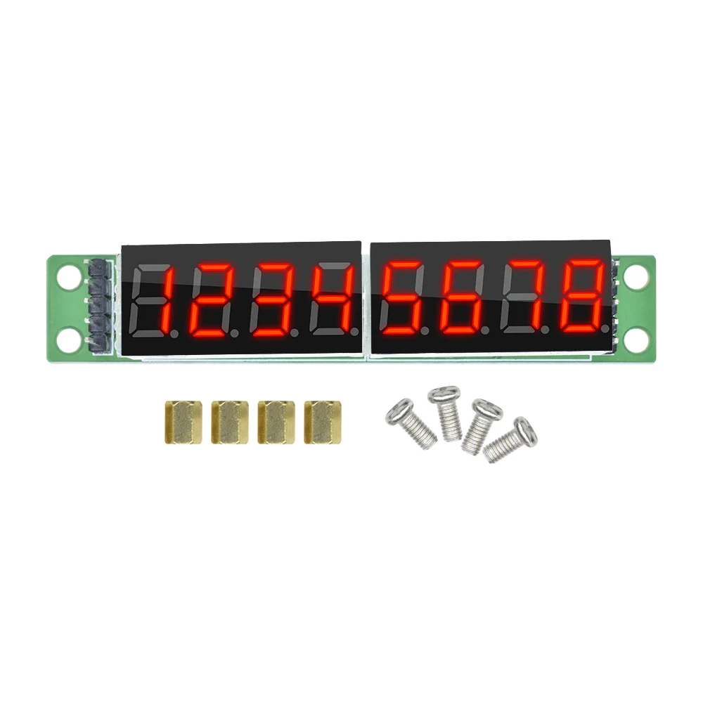
2. Onboard two 0.36 inch 4-bit integrated common cathode digital tubes
3. Two or more modules can be cascaded
4. Four positioning holes with a diameter of 3.6mm
5. Module supply voltage DC3.3V or 5V
6. Module compatible with 5V/3.3V microcontroller (STC51/AVR/STM32)
Special note
1. Do not connect VCC to GND incorrectly to avoid burning chips.
2.51 Microcontroller PO port needs to be connected to the pull resistance, if your microcontroller is not connected to the pull resistance, you can connect the data line to other ports.
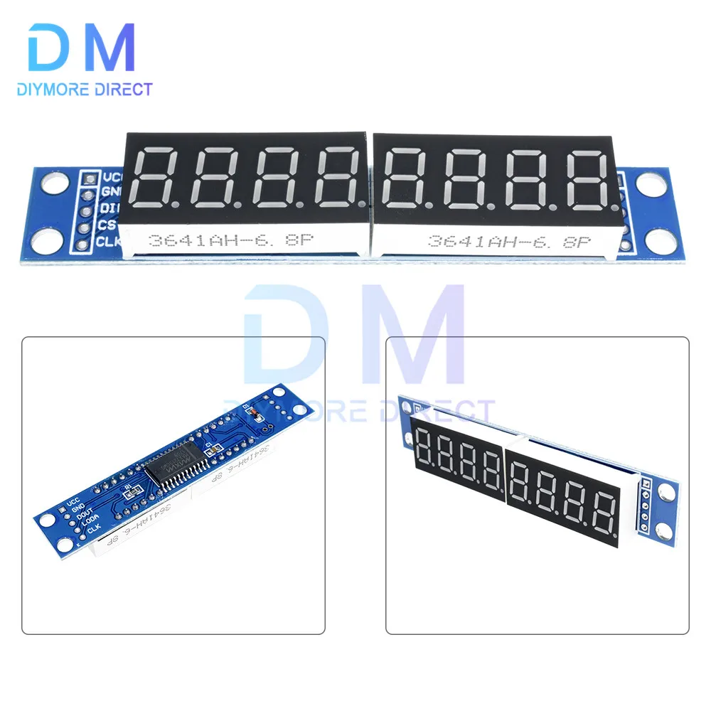
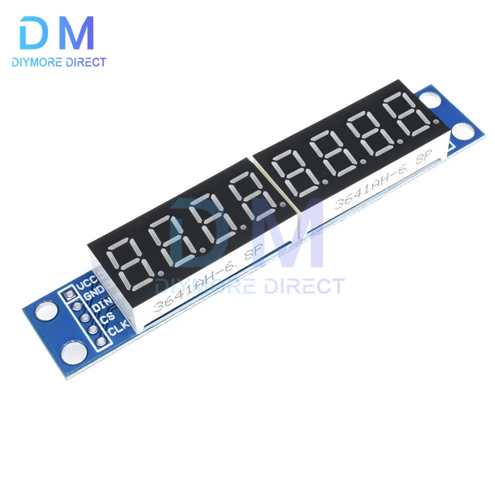
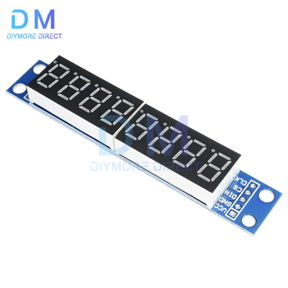
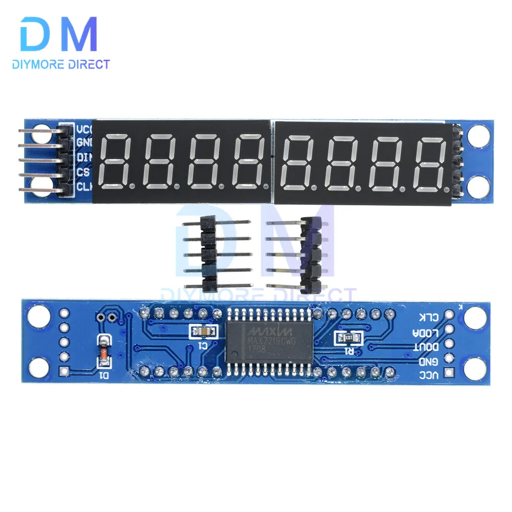
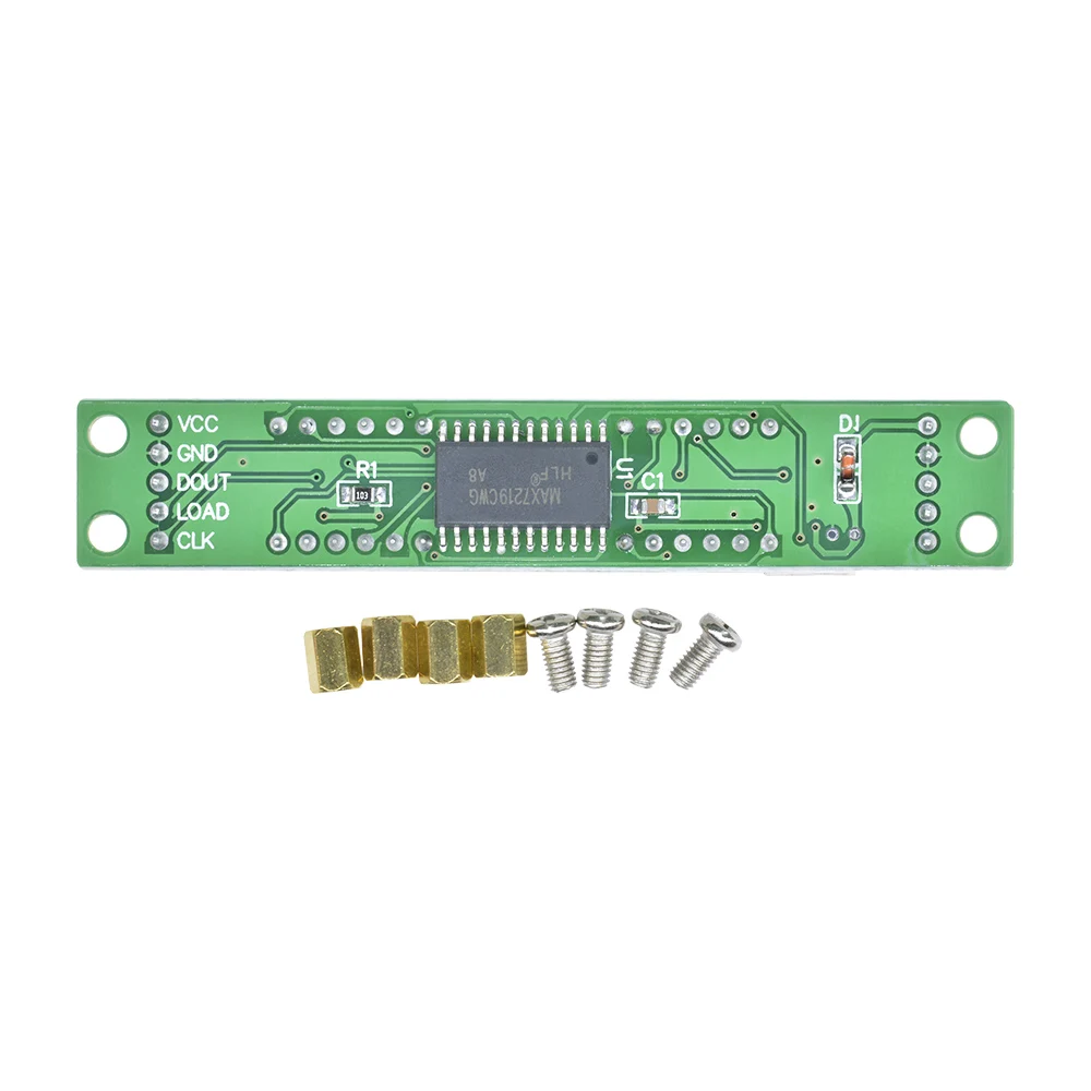
Green board:
Model: MAX7219
Color: Green board
Features: 150μA low power off mode, analog and digital brightness control, scan limit register allowing users to display 1-8 bit data, LED light detection mode.
Only three IO ports are needed to drive eight nixie tubes.
Fixed copper bolt four corner PCV plate, can effectively prevent short circuit accidents.
0.36 "four digital tube total negative LED.
Module support: 5v/3.3v microcontroller (51/AVR/STM32...)
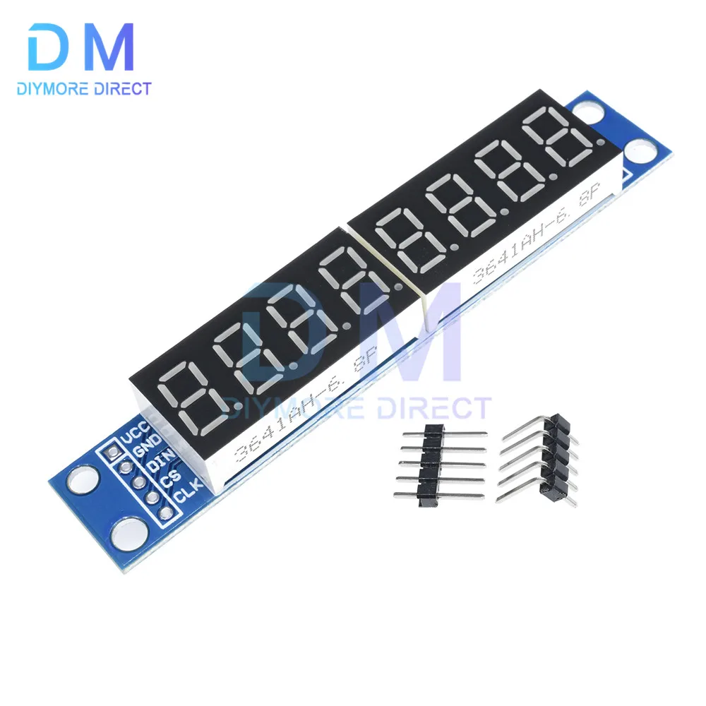
Wiring instructions (for example, for a program, you can select any IO port definition that can be modified in the program) :
VCC → 5V
Ground to ground
DIN → P00
CS → P01
Clock → P02
 Red Board:
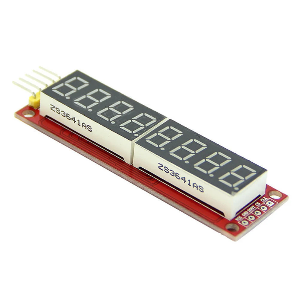
100% brand new, high quality
Power supply: 5V
Material: PCB + electronic components
Size: 76*21*11mm/2.99*0.8*0.43"
Wiring instructions (program, for example, you can choose any IO port definition that can be modified in the program):
VCC→5V
GND ground →
DIN→P1.0
CS→P1.1
CLK→P1.2
Notice:
Do not reverse VCC and GND, so as not to burn the chip
The P0 port of the 51 microcontroller needs a pull-up resistor. If your device does not have a pull-up resistor, you can connect to the data lines of other ports.
Free Shipping Over $199
- Standard Shipping: Standard Shipping (12–18 Business Days)
- Express Shipping: Expedited Shipping (5–9 Business Days)
- Free Shipping: Orders over $199 qualify automatically
- Tracking: Full tracking number provided for all orders
30-Day Return Policy
- Returns: 30-day hassle-free return window
- Condition: Items must be unused and in original packaging
- Refund: Full refund processed within 3-5 business days
Why Choose Us?
- Factory Direct: ISO/TS 16949 certified manufacturer
- Quality: 100% electrical continuity tested before shipment
- Experience: 15+ years in automotive connector industry
- Support: Professional technical support available

You may also like
Blog posts
Title
An excerpt of your blog post's content
Title
Date|Author
Subscribe to our emails
Be the first to know about new collections and special offers.