

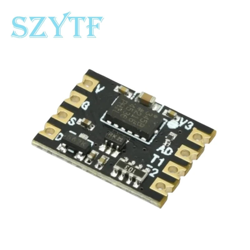
ADXL345 Module Digital 3-axis Gravity Acceleration Tilt Module IC2 Communication
1pcs
$17.51
Sale price
$17.51
Regular price
$0.00
Skip to product information


ADXL345 Module Digital 3-axis Gravity Acceleration Tilt Module IC2 Communication
$17.51
Sale price
$17.51
Regular price
$0.00
Description
SPECIFICATIONS
Application: Computer
Brand Name: SZYTF
Choice: yes
Condition: New
Dissipation Power: n/a
High-concerned chemical: none
Operating Temperature: n/a
Origin: Mainland China
Supply Voltage: n/a
Type: Module
is_customized: Yes
1. Product Profile:
ADX345 acceleration module is based on ultra-low power ADZ345 triaxial motion processing chip, which integrates peripheral LDO, I2c pull-up resistor and level switching circuit. It expands two rows of gold row pinholes and stamp holes with 2.54mnn spacing, which is convenient for users to weld and extend, and can also be directly attached to users' products. The module adopts r2ac communication. Support wide operating voltage. Use braided packing.
ADZ345 chip is a small and thin ultra-low power 3-axis accelerometer with high resolution (13 bits) and measuring range of ±16g. The digital output data is in 16-bit binary complement format and can be accessed via SPI(3-wire or 4-wire) or I2 digital interface. ADXL345 is ideal for mobile device applications. It can be used to measure static gravity acceleration in tilt detection applications, as well as dynamic acceleration due to motion or impact. It has a high resolution (3.9mg/LSB) and is capable of measuring tilt changes of less than 1.o°. The device provides a variety of special detection functions. The active and brown activity detection functions detect motion by comparing the acceleration on any axis with a user-set value. The knock detection function can detect single and double vibration in any direction. The free fall detection function detects whether the device is falling. These functions can be mapped independently to one of the two interrupt output pins. The integrated memory management system uses a three-stage first-in-first-out (FIFO) buffer that can be used to store data, thereby minimizing host processor load and reducing overall system power consumption.
Low power mode supports motion-based intelligent power management for threshold sensing and motion acceleration measurement at very low power consumption. ADXZL345 adopts 3mn×5 nn×1,14 pin small ultra-thin plastic package.
2. Main features:
Ultra-low power consumption: when VDD= 2.5V (typical value >, IC as low as 23u in measurement mode and 0.14A in standby mode, power consumption automatically proportional to bandwidth
Operating voltage range: 2.0v to 5.5v
I2c digital interface for communication
Measurement range is optional by serial command
Bandwidth is optional by serial command
User optional resolution
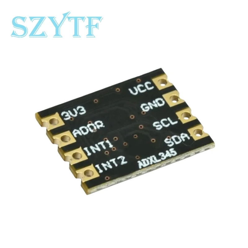
3. Foot position description:
VCC: power input
GND: power source
SCL: I2C clock, inner 10K pull-up
SDA: I2C data, internal 10K pull-up
INT2: interrupts output pin 2
IMT1: interrupts output pin 1
ADDR: Address configuration pin, black drop low level
3v3:3.3V output pin
4. Application field:
(1) Single power data acquisition system
(2) Instruments and meters
(3) Process control
(4) Battery power supply system
(5) Medical instruments
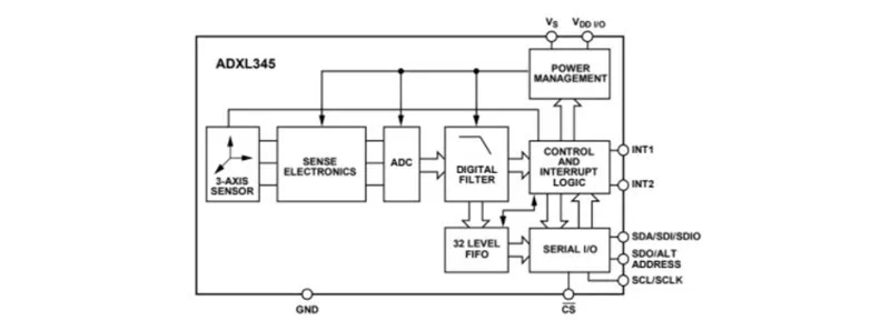
5. Internal block diagram of ADXL.345:
6. Function introduction:
This module reads data through the I2C interface. The I2c device address is b1010011X and the length is 7 bits. The last X bit of the 7-bit address is the read/write bit. If the ADDR is connected to 3.3v, the address is b0011101x and the length is 7 bits.
7. INT interrupt pin:
ADXL345 provides two output pins for driving interrupts :IMT1 and INT2. Both interrupt pins are push-pull low impedance pins. Interrupt pins are configured to be active at high levels by default. Set the INT_INVERT bit in the clamor DATA_FORMAT register (address ox31), which can be changed to be active at low level. All functions can be used at the same time, however, some functions may require shared interrupt pins. Set the appropriate bit of INT_ENAELE register (address ox2E), interrupt enabled, map to IMNT1 pin or INT2 pin, depending on the contents of the INT_MAP register (address ox2F). When initially configuring interrupt pins, it is recommended that pre-interrupt completion functions and interrupt mapping be enabled. When changing the interrupt configuration, you are advised to disable the interrupt by clearing the corresponding bit of the IMT_ENABLE register, and then enable the interrupt function to configure the function again. When interrupt is disabled, function configuration helps prevent interrupt accidents. Read the data register (address ox32 to address ox37), or read the remaining interrupts in the INT_SOURCE register (address ox30), latch and clear interrupt functions before the data dependent interrupt condition expires.
8. Offset calibration:
The accelerometer is mechanical and contains elements that can move freely. These moving parts are very sensitive to mechanical stress, much more so than solid-state electronics. The og offset or offset is an important accelerometer metric because it defines the baseline used to measure acceleration. Additional stresses may be applied when assembling a system containing an accelerometer. These stresses may result from, but are not limited to, the application of circuit board stresses during component welding, installation, and any mixture on the component. If calibration is necessary, it is recommended to do so after system assembly to compensate for these effects.
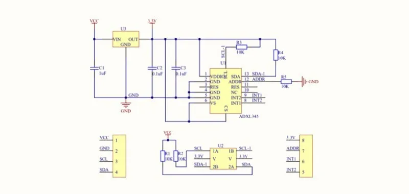
9. Application schematic diagram:
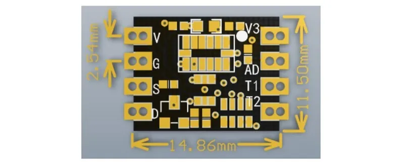
10. Product size:
Free Shipping Over $199
- Standard Shipping: Standard Shipping (12–18 Business Days)
- Express Shipping: Expedited Shipping (5–9 Business Days)
- Free Shipping: Orders over $199 qualify automatically
- Tracking: Full tracking number provided for all orders
30-Day Return Policy
- Returns: 30-day hassle-free return window
- Condition: Items must be unused and in original packaging
- Refund: Full refund processed within 3-5 business days
Why Choose Us?
- Factory Direct: ISO/TS 16949 certified manufacturer
- Quality: 100% electrical continuity tested before shipment
- Experience: 15+ years in automotive connector industry
- Support: Professional technical support available

You may also like
Blog posts
Title
An excerpt of your blog post's content
Title
Date|Author
Subscribe to our emails
Be the first to know about new collections and special offers.