

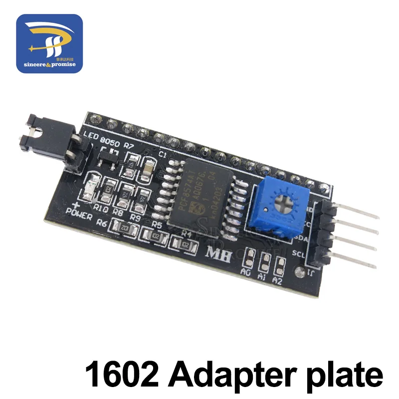
LCD Display Board Module 1602 2004 12864 PCF8574T PCF8574 IIC/I2C Interface Adapte Plate 5V Blue/Yellow Green Screen For Arduino
12864 Blue
$32.45
Sale price
$32.45
Regular price
$0.00
Skip to product information






LCD Display Board Module 1602 2004 12864 PCF8574T PCF8574 IIC/I2C Interface Adapte Plate 5V Blue/Yellow Green Screen For Arduino
$32.45
Sale price
$32.45
Regular price
$0.00
Description
SPECIFICATIONS
Brand Name: sincere&promise
Choice: yes
Display Mode: 1602
High-concerned chemical: none
Model Number: LCD Display
Origin: Mainland China
Resolution: 16*2
Type: Character
is_customized: Yes
semi_Choice: yes

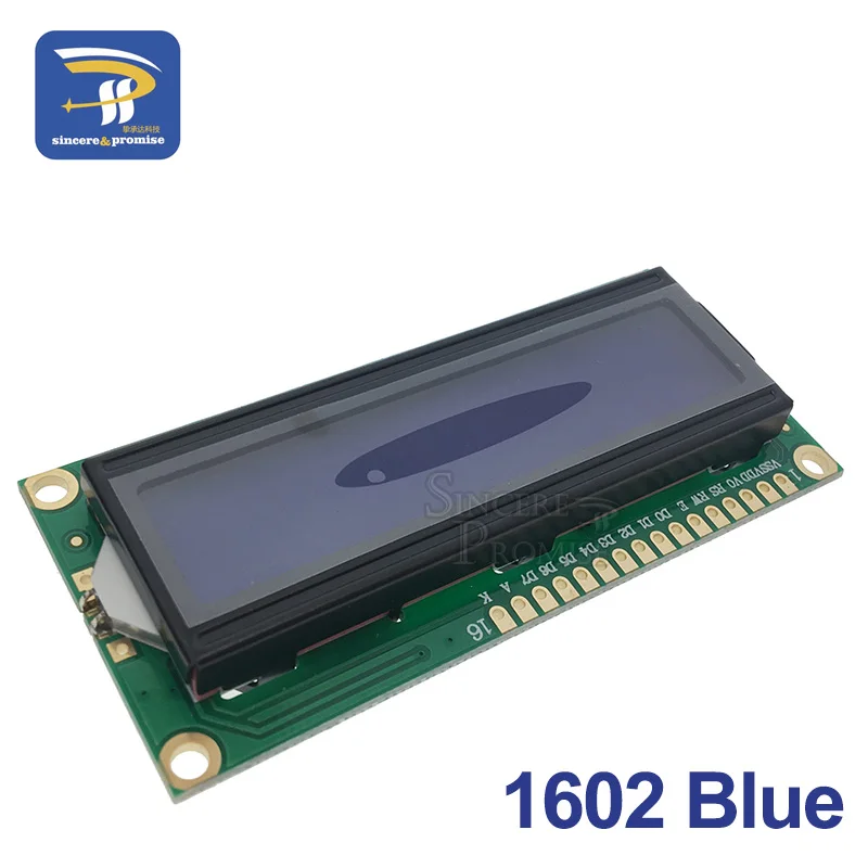
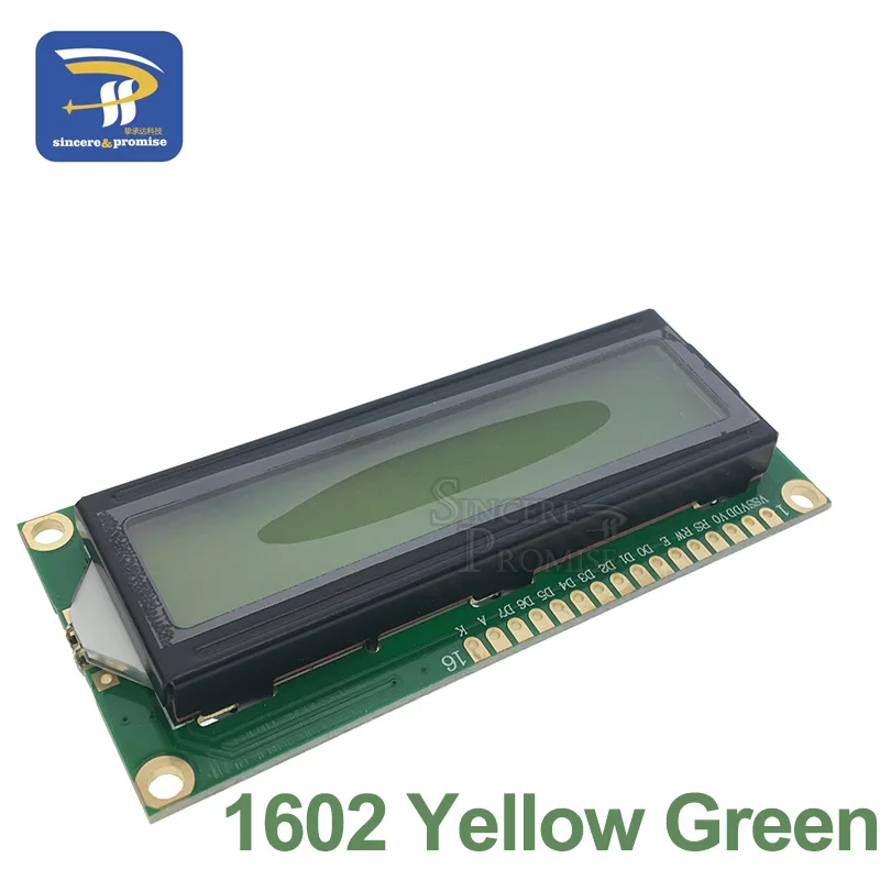
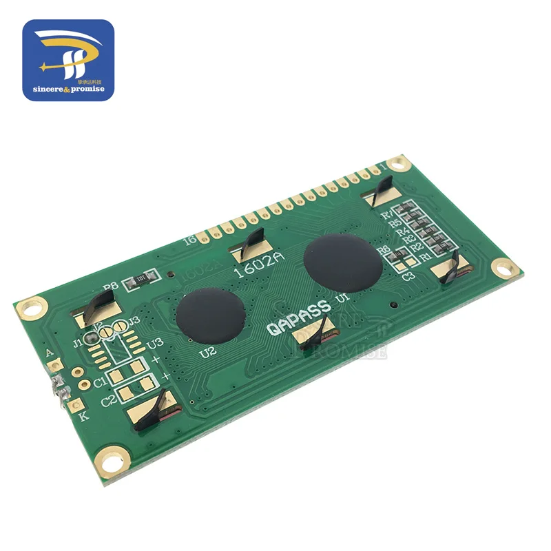
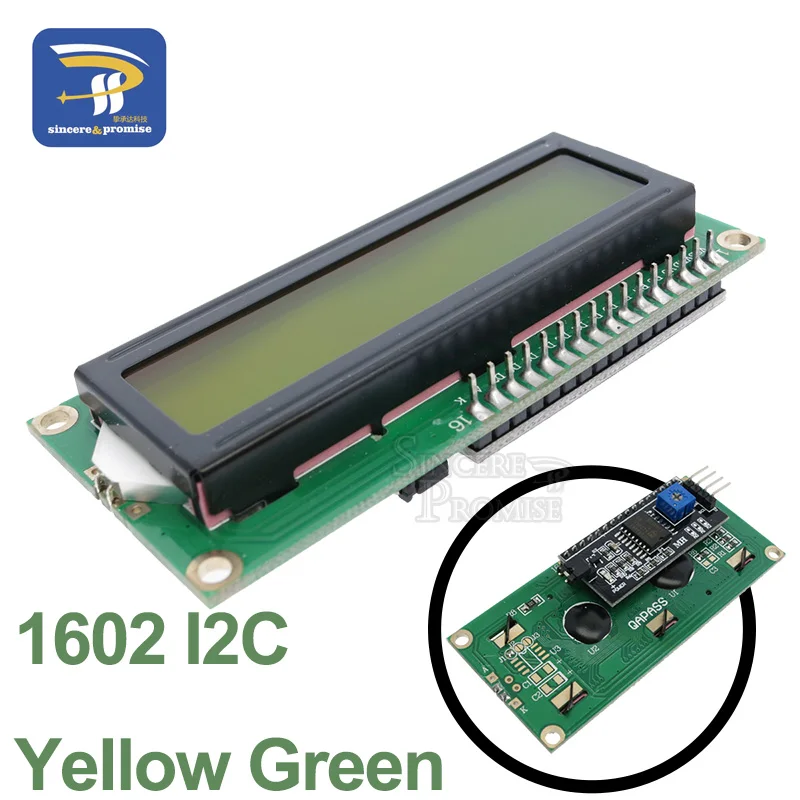
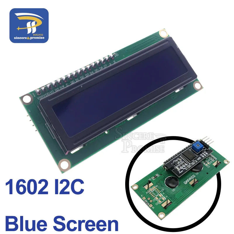
1602A Blue/ Yellow-Green
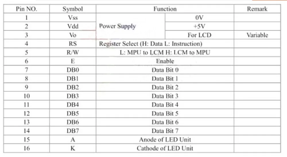
1602 the standard 16 feet interface, among them:
1 foot: for to power VSS
2 feet: VDD take 5 V is power
3 feet: V0 for LCD contrast the adjustment, and then when the power is the weakest contrast, grounding the power supply highest contrast, high contrast can produce the "ghost", when used, can pass a 10 K adjust potentiometer contrast
4 feet: RS for registers choice, high electric usually choose data registers, low electric usually choose instruction register.
5 feet: R/W signal lines for reading and writing, high electric usually are read operation, low electricity at ordinary times for write operation. When the RS and RW together for low electricity can be written instructions at ordinary times, or displays address, when RS for low level for high electricity can usually RW read busy signals, when RS for high level for the low electricity can usually RW write data.
6 feet: E end to make can end, when E is driven by high level jump into low electricity at ordinary times, LCD module executive order.
7 to 14 feet: D0 ~ D7 for eight two-way data cables.
15 feet: backlighting power positive
16 feet: backlighting power negative
1602 LCD module of the internal character happen memory (CGROM) has already been stored 160 different dot matrix characters graphics, as is shown in table 1, these characters have: Arabic numerals, English letters of the case, the commonly used symbols, such as Japanese and under A false name, every character has A fixed code, such as capital letter English the letter "A" code is 01000001 B (41 H), shows the address of the 41 modules H dot matrix characters graphic display out, and we can see the letter "A".
The following is the second line LCD module in the position of the first character that the letter "A" program: ORG 0000 H
RS EQU P3.7; Determining the specific hardware connection
RW EQU P3.6; Determining the specific hardware connection
E EQU P3.5; Determining the specific hardware connection
MOV P1, # 00000001 B; Screen clearing and cursor reset
ACALL ENABLE; Call to order a subroutine
MOV P1, # 00111000 B; Set the display mode: eight 2 line 5 x7 dot matrix
ACALL ENABLE; Call to order a subroutine
MOV P1, # 00001111 B; The display of open and cursor away, and the cursor allows flash
ACALL ENABLE; Call to order a subroutine
MOV P1, # 00000110 B; Words don\'t move, the cursor to move to the right
ACALL ENABLE; Call to order a subroutine
MOV P1, # 0 C0H; Write show starting address (the second line the first position)
ACALL ENABLE; Call to order a subroutine
MOV P1, # 01000001 B; Letters A code
SETB RS; RS = 1
CLR RW; RW = 0; Ready to write data
CLR E; E = 0; Executive show command
ACALL DELAY; Judge LCD module is busy?
SETB E; E = 1; Display complete, and the program to park
AJMP $
ENABLE:
CLR RS; Write control command of a subroutine
CLR RW
CLR E
ACALL DELAY
SETB E
RET
DELAY:
MOV P1, # 0 FFH; Judge whether the busy liquid crystal display subroutine
CLR RS
SETB RW
CLR E
NOP
SETB E
JB P1.7, DELAY; If P1.7 for high level said busy circulation wait
RET
END
Program in the beginning of LCD module function initialized Settings, agreed that the format. Pay attention when the cursor is automatic display characters move to the right, without human intervention, and every time input commands are called first judge LCD module of the procedure is busy DELAY, and then enter the address of the display position 0 C0H, finally to show character input A code 41 H.
SMC1602A (16 * 2) simulation mouth line connection mode
Connection line:
- - - - - - - - - - - - - - - - - - - - - - - - - -
| LCM-51 | LCM-51 | LCM- - - 51 |
- - - - - - - - - - - - - - - - - - - - - - - - |
| DB0- - -P1.0 | DB4- - -P1.4 | RW- - - -P2.0 |
| DB1- - -P1.1 | DB5- - -P1.5 | RS- - - -P2.1 |
| DB2-P1.2 | DB6- - -P1.6 | E- - - - P2.2 |
| DB3- - -P1.3 | DB7- - -P1.7 | VLCD take 1 K resistance to the GND |
- - - - - - - - - - - - - - - - - - - - - - - - - -
[note: AT89S52 devices use 12 M crystals]
= = = = = = = = = = = = = = = = = = = = = = = = = = = = = = = = = = = = = = = = = = = = = = = = = = = = = = = = = = = = = * /
# define LCM_RW P2_0 / / definition pin
# define LCM_RS P2_1
# define LCM_E P2_2
# define LCM_Data P1
# define Busy 0 x80 / / used to test LCM status word in Busy logo
# I nclude
Void WriteDataLCM (unsigned char WDLCM);
Void WriteCommandLCM (unsigned char WCLCM, BuysC);
Unsigned char ReadDataLCM (use void);
Unsigned char ReadStatusLCM (use void);
Void LCMInit (use void);
Void DisplayOneChar (unsigned char X, unsigned char Y, unsigned char DData);
Void DisplayListChar (unsigned char X, unsigned char Y, unsigned char code * DData);
Void Delay5Ms (use void);
Void Delay400Ms (use void);
Unsigned char code uctech [] = {" uctech ");
Unsigned char code net [] = {" uctech. Icpcn. Com ");
Void main (use void)
{
Delay400Ms (); / / start waiting, and speak into the work of the state LCM
LCMInit (); / / LCM initialization
Delay5Ms (); / / delay a moment (don\'t)
DisplayListChar (0, 5, uctech);
DisplayListChar (0, 0, net);
ReadDataLCM (); / / test the words in meaningless
While (1);
}
/ / write data
Void WriteDataLCM (unsigned char WDLCM)
{
ReadStatusLCM (); / / testing busy
LCM_Data = WDLCM;
LCM_RS = 1;
LCM_RW = 0;
LCM_E = 0; / / if crystals too high speed in small add after delay
LCM_E = 0; / / delay
LCM_E = 1;
}
/ / write instructions
Void WriteCommandLCM (unsigned char WCLCM, BuysC) / / BuysC 0 ignore busy detection
{
If (BuysC) ReadStatusLCM (); / / according to need to detect busy
LCM_Data = WCLCM;
LCM_RS = 0;
LCM_RW = 0;
LCM_E = 0;
LCM_E = 0;
LCM_E = 1;
}
/ / read data
Unsigned char ReadDataLCM (use void)
{
LCM_RS = 1;
LCM_RW = 1;
LCM_E = 0;
LCM_E = 0;
LCM_E = 1;
Return (LCM_Data);
}
/ / read state
Unsigned char ReadStatusLCM (use void)
{
LCM_Data = 0 xFF;
LCM_RS = 0;
LCM_RW = 1;
LCM_E = 0;
LCM_E = 0;
LCM_E = 1;
While (LCM_Data & Busy); / / testing busy signals
Return (LCM_Data);
}
Void LCMInit (use void) / / LCM initialization
{
LCM_Data = 0;
WriteCommandLCM (0, 0 x38); / / three times the display mode Settings, does not measure busy signals
Delay5Ms ();
WriteCommandLCM (0, 0 x38);
Delay5Ms ();
WriteCommandLCM (0, 0 x38);
Delay5Ms ();
WriteCommandLCM (0 x38, 1); / / display mode Settings, began to demand that every time detection busy signals
WriteCommandLCM (0 x08, 1); / / disable display
WriteCommandLCM (0 x01, 1); / / display screen clearing
WriteCommandLCM (0 x06, 1); / / show cursor movement Settings
WriteCommandLCM (0 x0C, 1); / / show open and cursor Settings
}
/ / in the specified location displaying a character
Void DisplayOneChar (unsigned char X, unsigned char Y, unsigned char DData)
{
Y & = 0 x1;
X & = 0 xF; / / limit X is not greater than 15, Y is not greater than 1
If (Y) X | = 0 x40; / / when want to show the second when address + 0 x40;
X | = 0 x80; / / work out instruction code
WriteCommandLCM (X, 0); / / here don\'t test busy signal, send address
WriteDataLCM (DData);
}
/ / in the specified position shows a string of characters
Void DisplayListChar (unsigned char X, unsigned char Y, unsigned char code * DData)
{
Unsigned char ListLength;
ListLength = 0;
Y & = 0 x1;
X & = 0 xF; / / limit X is not greater than 15, Y is not greater than 1
While (DData [ListLength] > 0 x20) / / if arrive, the string is out
{
If (X < = 0 xF) / / X should be less than 0 xF
{
DisplayOneChar (X, Y, DData [ListLength]); / / show individual character
ListLength++;
X++;
}
}
}
/ / 5 ms delay
Void Delay5Ms (use void)
{
Unsigned int TempCyc = 5552;
While (TempCyc--
}
/ / 400 ms delay
Void Delay400Ms (use void)
{
Unsigned char TempCycA = 5;
Unsigned int TempCycB;
While (TempCycA--
{
TempCycB = 7269;
While (TempCycB--
};
Above program is for reference only!!!!!!
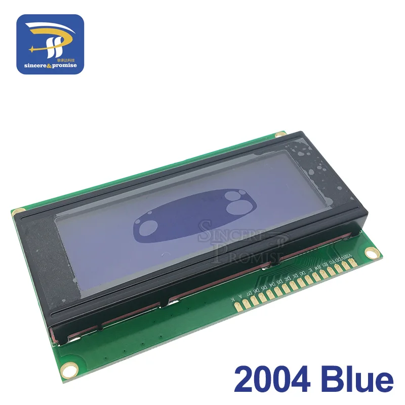
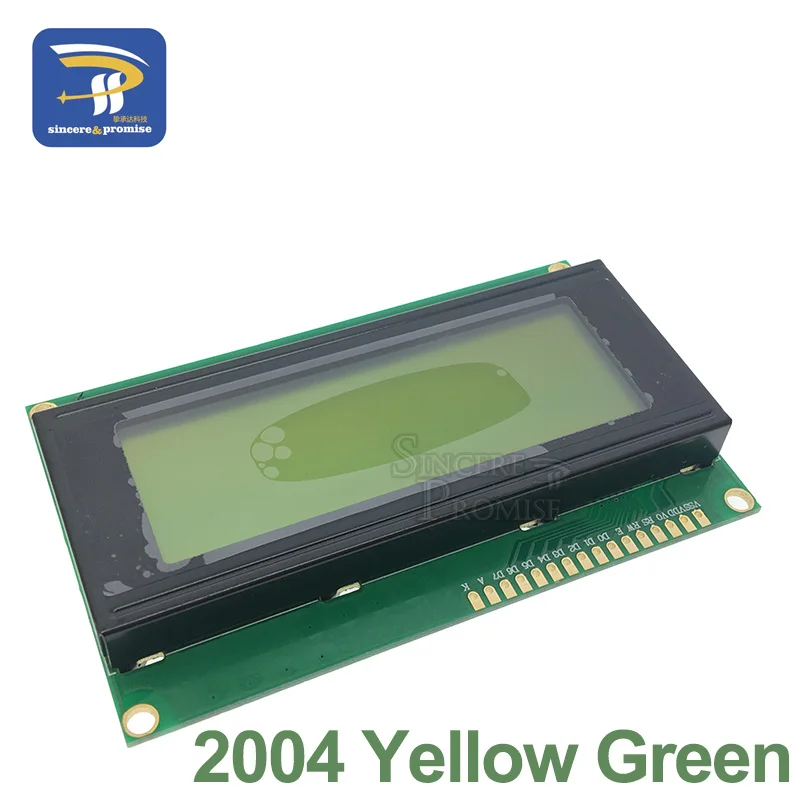
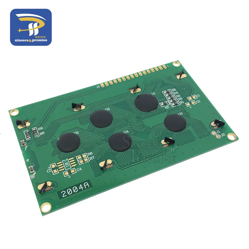
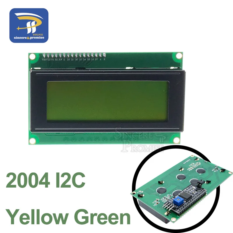
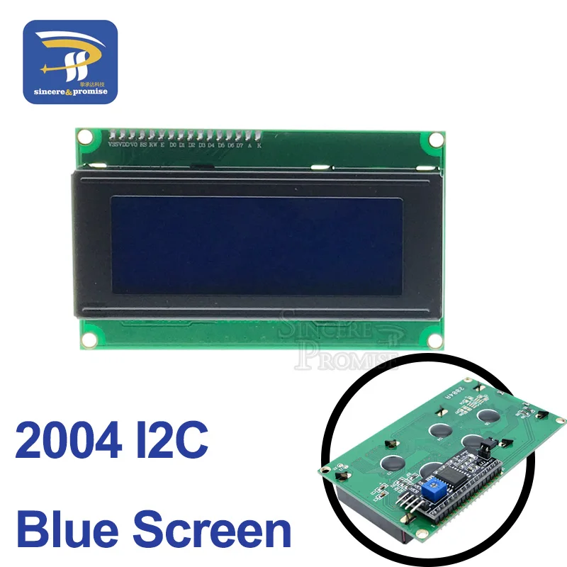
2004 Blue / Yellow-Green
Main technical parameters and display characteristics:
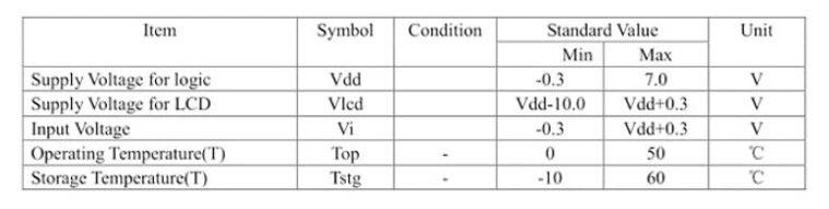
Power supply: VDD 5V
Display color: yellow green / blue screen
Display angle: 6: 00 hours direct LCD type: STN
Interface with MCU: 8-bit or 4-bit parallel/3-bit serial configuration LED backlight
A variety of software features: cursor display, screen shift, custom characters, sleep mode, etc.
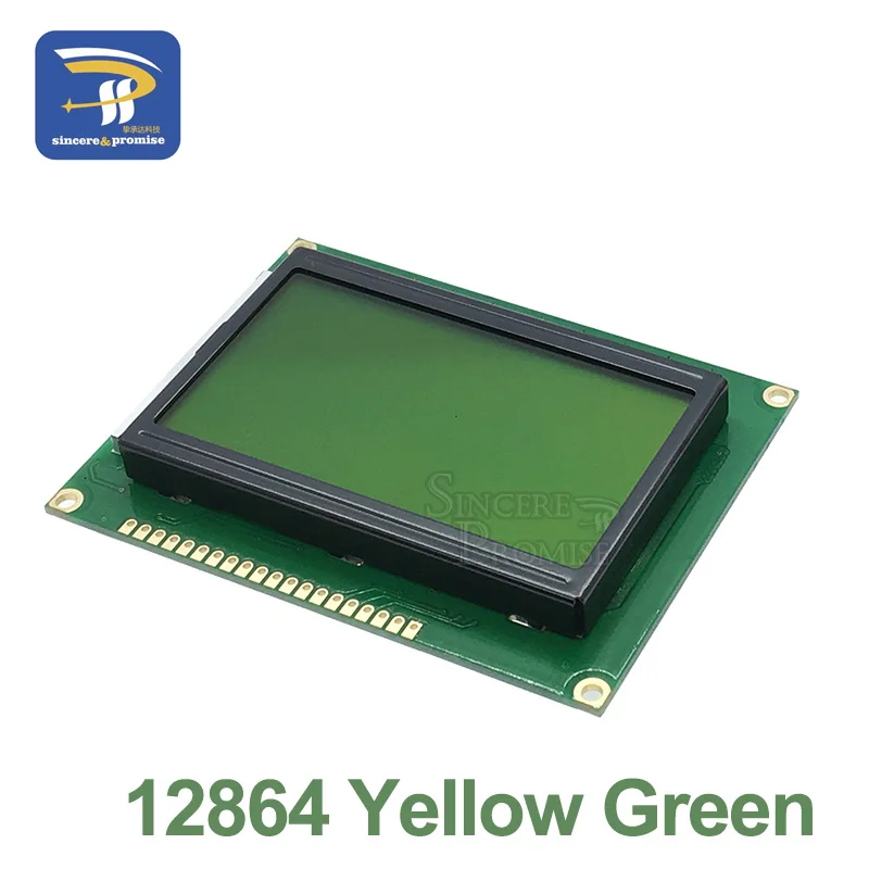
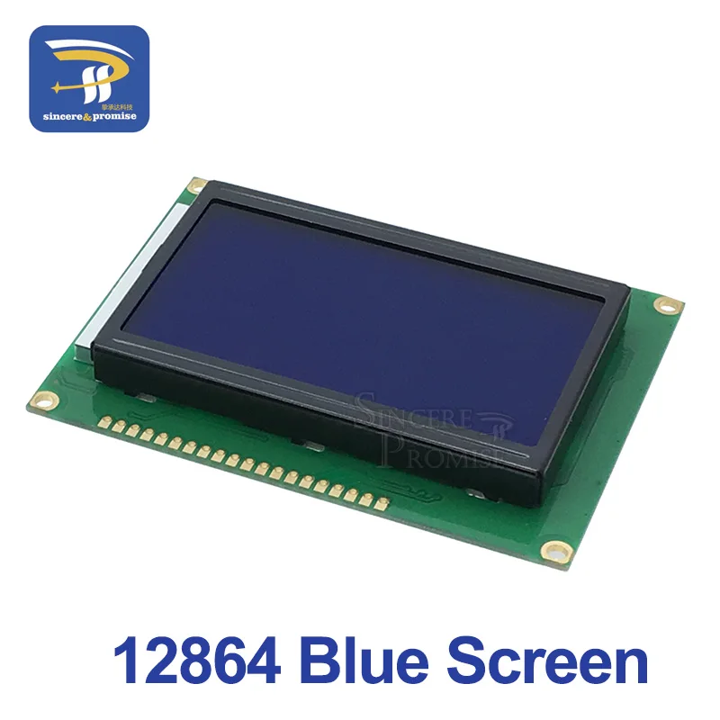
12864B blue/yellow-green
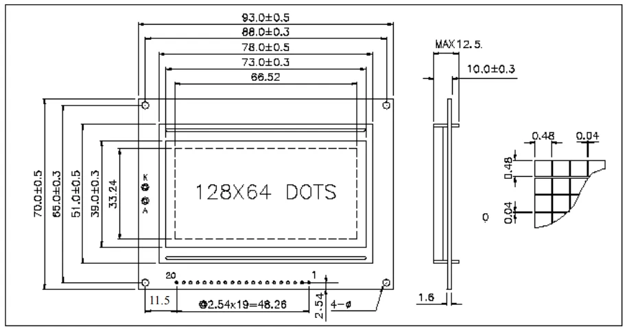
12864 Chinese kanji graphic dot matrix liquid crystal display module, can display Chinese characters and graphics, built-in 8192 Chinese characters (16X16 dot matrix), 128 characters (8X16 dot matrix) and 64X256 dot matrix display RAM (GDRAM).
Main technical parameters and display characteristics:
Power supply: VDD 3.3V~+5V (built-in boost circuit, no negative pressure required);
Display content: 128 columns x 64 rows
Display color: yellow green / blue screen
Display angle: 6: 00 hours direct view
LCD type: STN
Interface with MCU: 8-bit or 4-bit parallel/3-bit serial
Configuring LED backlighting
A variety of software features: cursor display, screen shift, custom characters, sleep mode, etc.
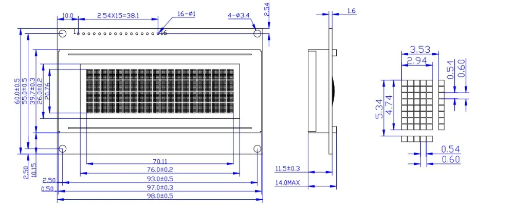
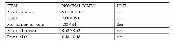
Dimensions: 93x70x 12.5mm
Sight Size: 73 x 39mm
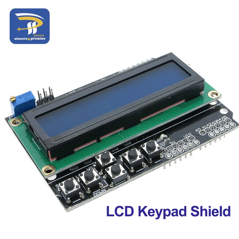
LCD Keypad Shield
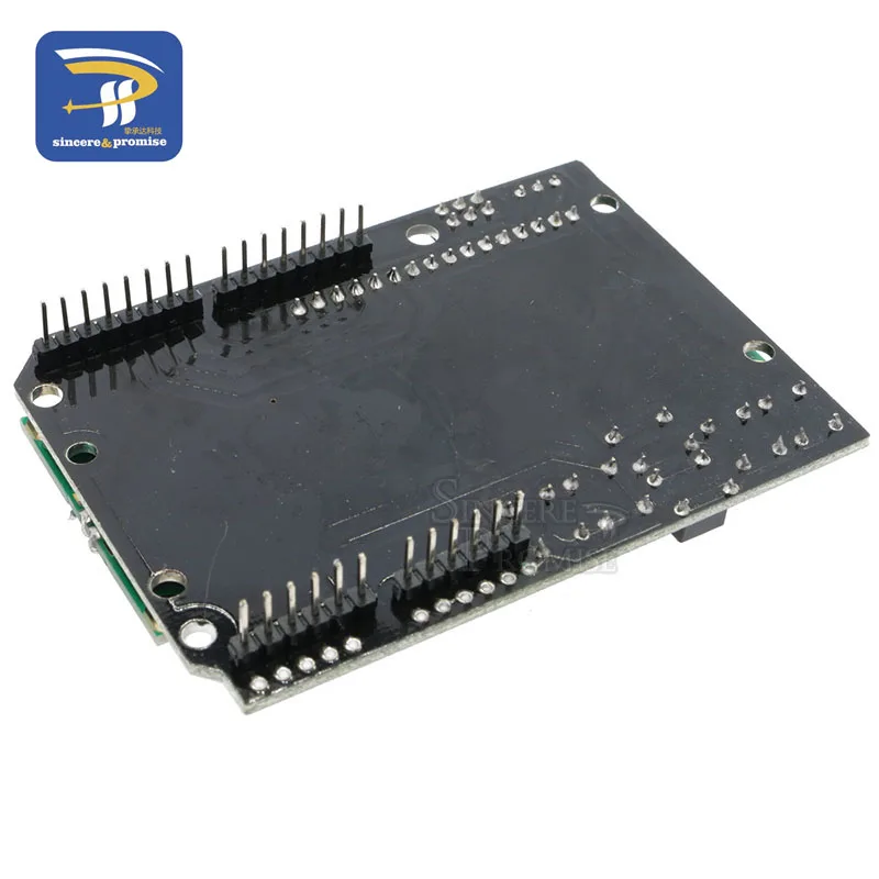
LCD Keypad Shield input-output expansion board using the two -line 16 character LCD with contrast adjustment and backlight , using an analog input port will complete five buttons , a reset button , unused IO ports are extended out of the reserve, make full use of IO ports . Occupancy figures port : PIN4 (DB4), 5 (DB5), 6 (DB6), 7 (DB7), 8 (RS), 9 (E), 10 ( backlight control ) , an analog button port A0. (LCD color is not specified, the random delivery. )
Used in conjunction with Roboduino :
Module debugging :
The LCD Keypad Shield plugged into the controller, then you need to download LCD4Bit_mod.h ( Right Save As ) library files to -0015 \ hardware \ libraries , and then compile the following test program and then downloaded to the initial use of LCD Keypad Shield , the first observation there is no LCD display character , if there is no contrast display characters that may be incorrect , you can use a flathead screwdriver to adjust RP1 ( clockwise rotation ) , the characters can be transferred to emerge clearly .
Professional anti-static packaging
Test renderings :
GP2D12 ranging code :
# include
LCD4Bit_mod lcd = LCD4Bit_mod (2);
char GP2D12;
char a, b;
char str1 [] = "Renge:";
char str2 [] = "Renge Over";
char str3 [] = "cm";
void setup ()
{
lcd.init ();
lcd.clear ();
lcd.printIn ("GP2D12 testing ...");
}
void loop ()
{
GP2D12 = read_gp2d12_range (1);
if (GP2D12> 80 | | GP2D12 <10)
{
lcd.cursorTo (2,0);
lcd.printIn (str2);
}
else
{
a = 0x30 + GP2D12/10;
b = 0x30 + GP2D12% 10;
lcd.cursorTo (2, 3);
lcd.printIn (str1);
lcd.print (a);
lcd.print (b);
lcd.printIn (str3);
}
delay (50);
}
float read_gp2d12_range (byte pin)
{
int tmp;
tmp = analogRead (pin);
if (tmp <3) return -1;
return (6787.0 / ((float) tmp - 3.0)) - 4.0;
}
Free Shipping Over $199
- Standard Shipping: Standard Shipping (12–18 Business Days)
- Express Shipping: Expedited Shipping (5–9 Business Days)
- Free Shipping: Orders over $199 qualify automatically
- Tracking: Full tracking number provided for all orders
30-Day Return Policy
- Returns: 30-day hassle-free return window
- Condition: Items must be unused and in original packaging
- Refund: Full refund processed within 3-5 business days
Why Choose Us?
- Factory Direct: ISO/TS 16949 certified manufacturer
- Quality: 100% electrical continuity tested before shipment
- Experience: 15+ years in automotive connector industry
- Support: Professional technical support available

You may also like
Blog posts
Title
An excerpt of your blog post's content
Title
Date|Author
Subscribe to our emails
Be the first to know about new collections and special offers.