

RF-Nano for Arduino Nano V3.0 TYPE-C USB Module Compatible ATmega328P CH340 Integrated NRF24L01 Wireless CH340 Module
RF-Nano TYPE-C
$29.48
Sale price
$29.48
Regular price
$0.00
Skip to product information


Product Introduction:
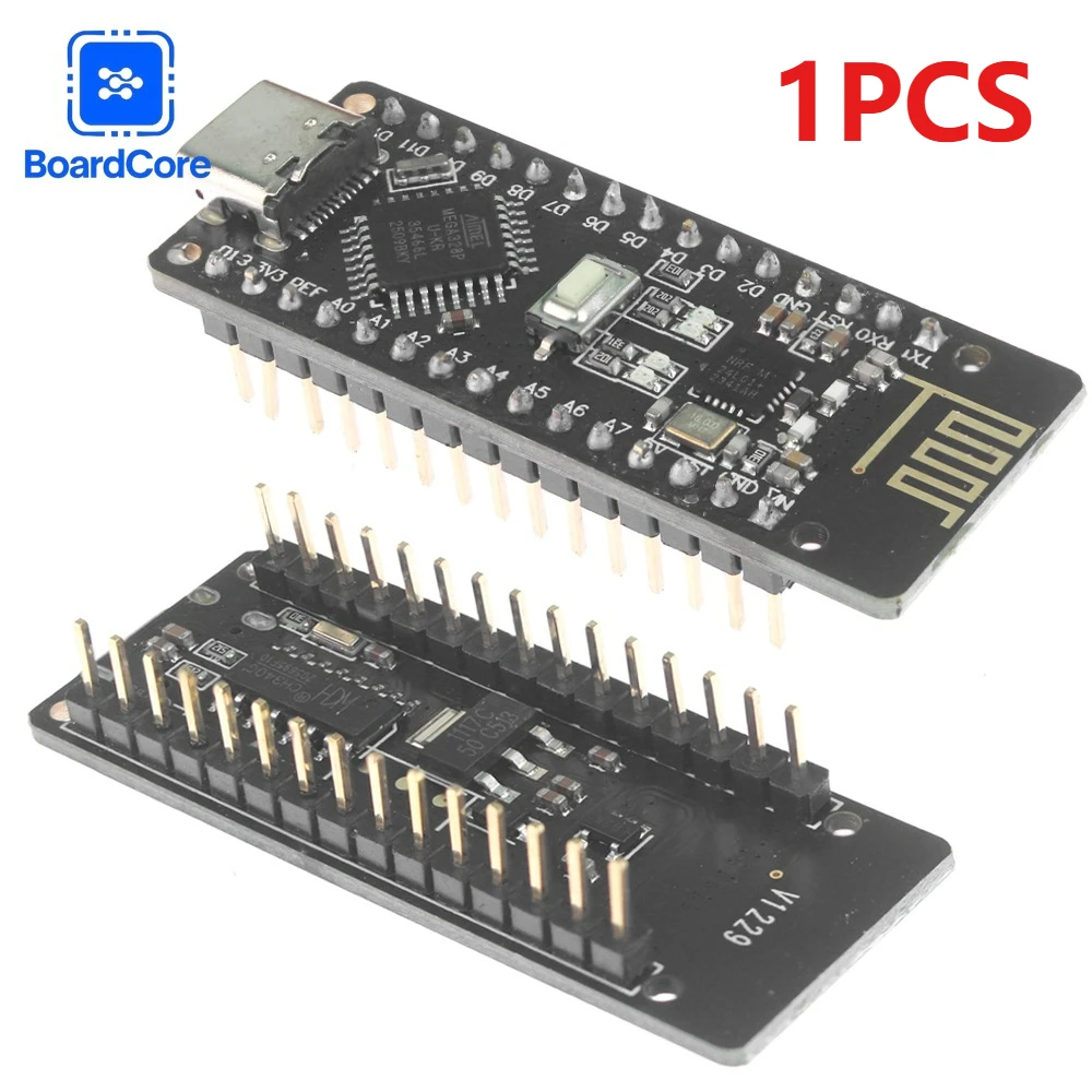
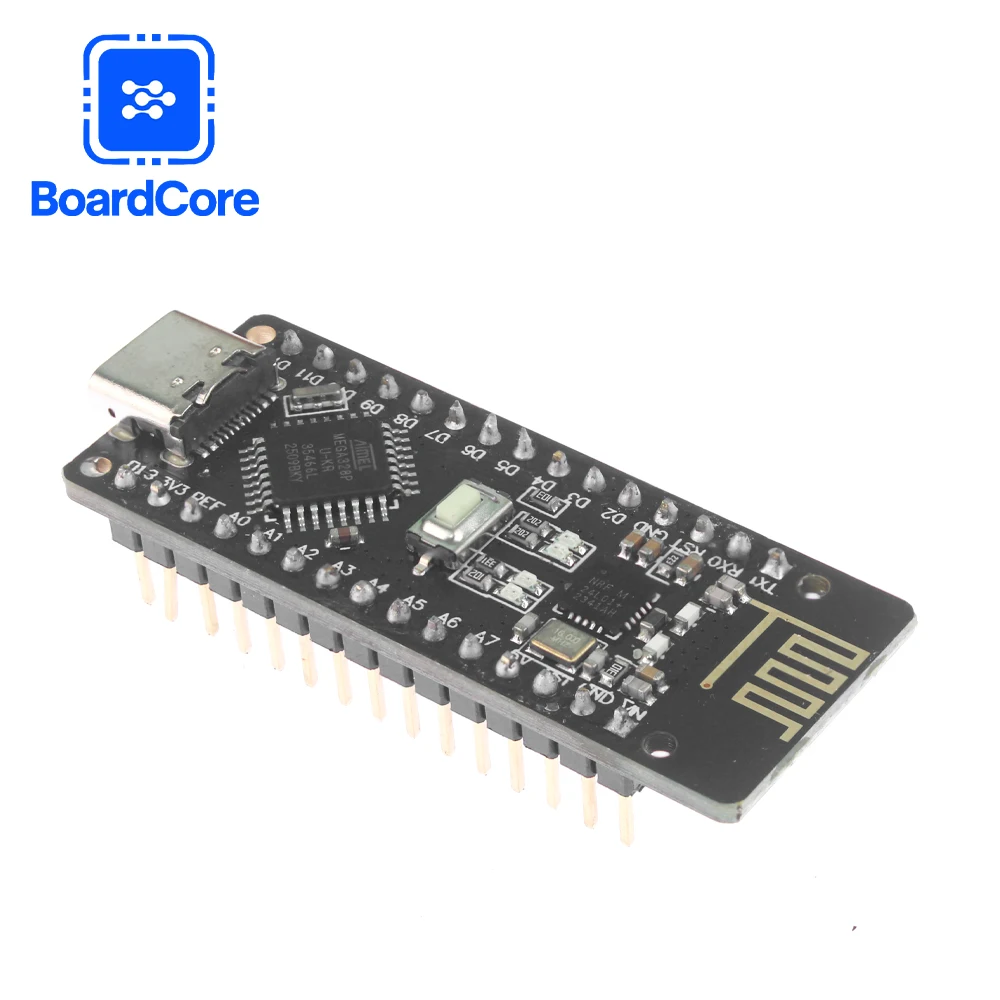
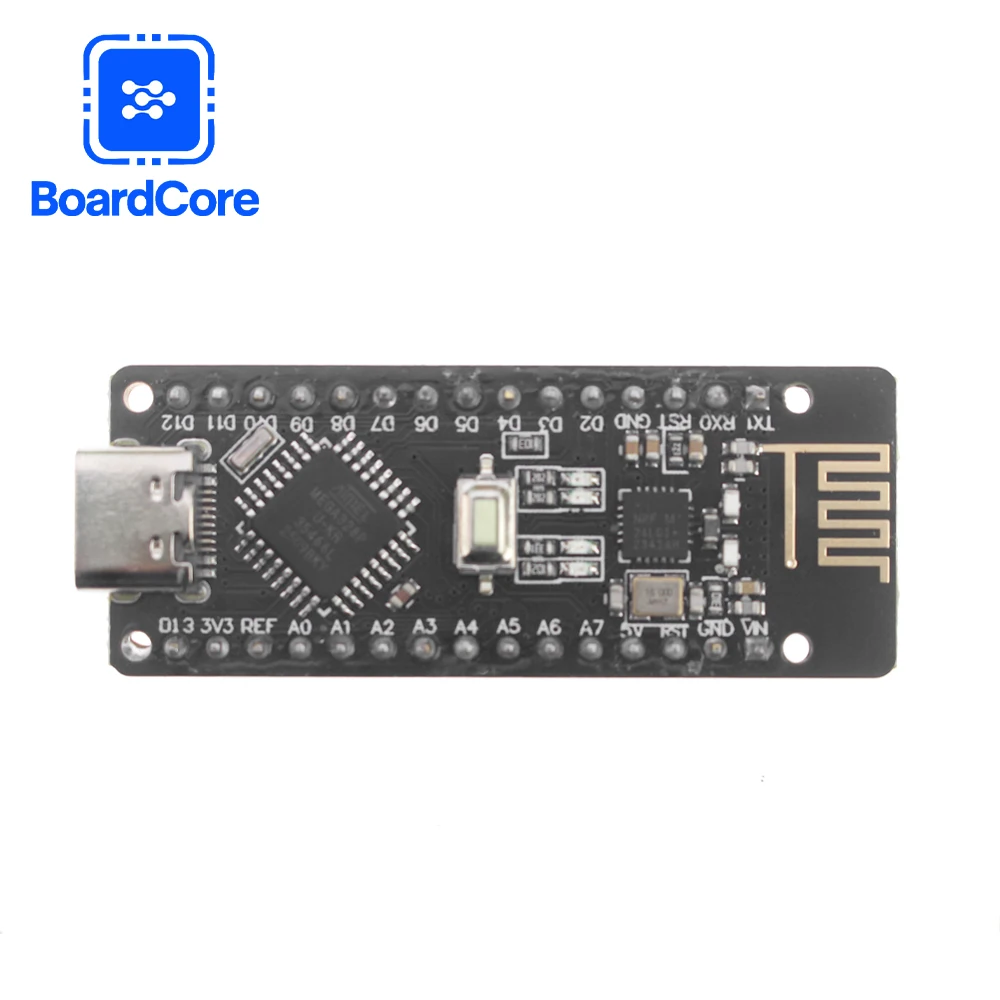
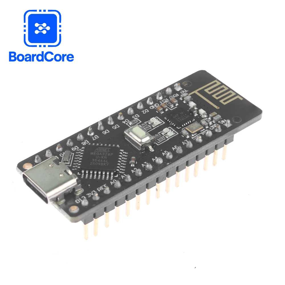
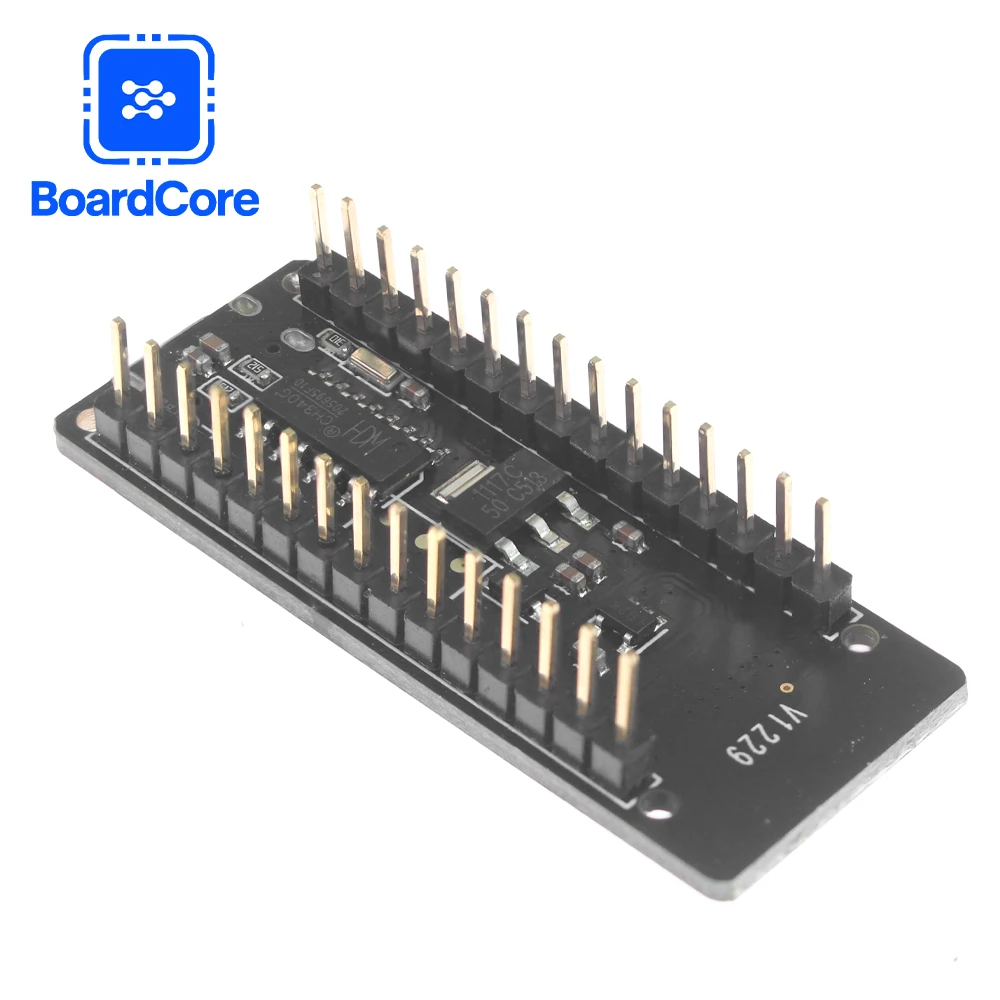
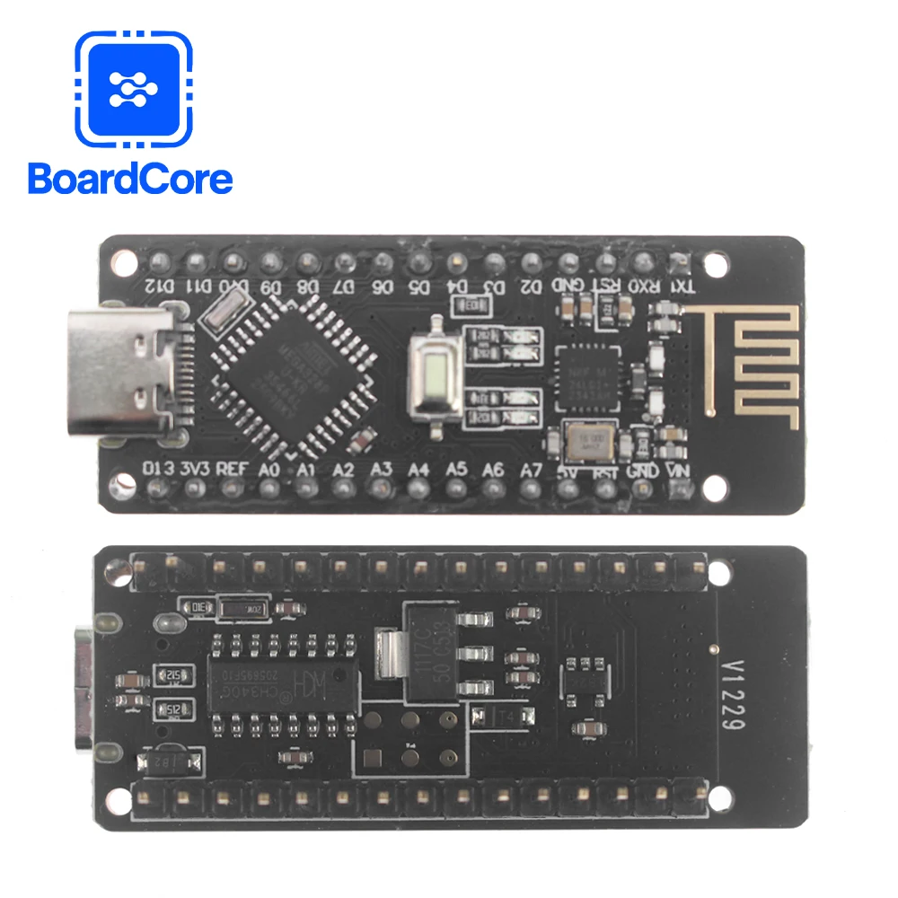
The RF-NANO board integrates the NRF24L01+ chip, which endows it with unlimited transmission and reception capabilities. It is equivalent to combining a regular Nano board with an NRF24L01 module into one, making it more convenient to use and smaller in size. The pins of RF-NAN0 are exactly the same as those of common Nano boards, making it convenient for transplantation.
Processor Introduction:
The Arduino RF.NANO microprocessor is the ATmega328(Nano3.0), featuring a USB-Micro interface. It has 14 digital input/output ports (6 of which can be used as PWM outputs), 8 analog inputs, a 16MHz crystal oscillator, and a USB-Micro port. An ICSP header and a reset button.
Processor :ATmega328
Operating voltage :5V Input voltage (recommended):7-12V Input voltage (range):6-20V Digital I0 pin :14(among which 6 channels are used as PWM output)(D0~D13
Analog input pins :6 (A0 to A5)
Dc current at pin I0 :40mA
Flash Memory:32KB(of which 2KB is used for bootloader)
SRAM: 2KB
EEPROM:1KB(ATmega328)
Usb-to-serial port chip :CH340
Working clock: 16 MHZ
Power supply:
The power supply methods for Arduino RF-Nano: power supply through the Micro-USB port and external vin connected to a 7-12V external DC power supply
Memory:
The ATmega328 includes 32KB of on-chip Flash, of which 2KB is used for the Bootloader. It also has 2KB of SRAM and 1KB of EEPROM.
Input/Output:
14-channel digital input and output ports: Working voltage is 5V, and each channel can output and connect a maximum current of 40mA. Each circuit is equipped with a 20-50K ohm internal pull-up resistor (not connected by default). In addition, some pins have specific functions.
Serial port signals RX(0), TX(1): Provide serial port receiving signals at TTL voltage levels, connected to the corresponding pins of FT232RI.
External interrupts (No. 2 and No. 3): Trigger interrupt pins, which can be set as rising edge, falling edge, or triggered simultaneously. Pulse Width Modulation PWM(3, 5, 6, 9, 10, 11): Provides 6 channels of 8-bit PWM output.
SPI(10(SS), 11(MOSI), 12(MISO), 13(SCK)):SPI communication interface. LED(No. 13):A reserved interface specifically designed for testing leds in Arduino. When the output is high, the LED lights up; conversely, when the output is low, the LED turns off.
6-channel analog input A0 to A5: Each channel has a resolution of 10 bits (i.e., the input has 1024 different values). The default input signal range is 0 to 5V, and the input upper limit can be adjusted through AREF. In addition, some pins have specific functions.
TWI interface (SDA A4 and SCL A5): Supports communication interface (compatible with I2C bus).
AREF: Reference voltage for analog input signals.
Reset: Reset the single-chip microcomputer chip when the signal is low.
Communication interface:
Serial port: The built-in UART of ATmega328 can communicate with the outside through the digital ports 0(RX) and 1(TX) via serial port.


RF-Nano for Arduino Nano V3.0 TYPE-C USB Module Compatible ATmega328P CH340 Integrated NRF24L01 Wireless CH340 Module
$29.48
Sale price
$29.48
Regular price
$0.00
Description
SPECIFICATIONS
Application: Computer
Brand Name: NONE
Choice: yes
Condition: New
Dissipation Power: ..
High-concerned chemical: none
Operating Temperature: RF-Nano
Origin: Mainland China
Package: SMD
Supply Voltage: ..
Type: Voltage Regulator
is_customized: Yes
Product Introduction:
The RF-NANO board integrates the NRF24L01+ chip, which endows it with unlimited transmission and reception capabilities. It is equivalent to combining a regular Nano board with an NRF24L01 module into one, making it more convenient to use and smaller in size. The pins of RF-NAN0 are exactly the same as those of common Nano boards, making it convenient for transplantation.
Processor Introduction:
The Arduino RF.NANO microprocessor is the ATmega328(Nano3.0), featuring a USB-Micro interface. It has 14 digital input/output ports (6 of which can be used as PWM outputs), 8 analog inputs, a 16MHz crystal oscillator, and a USB-Micro port. An ICSP header and a reset button.
Processor :ATmega328
Operating voltage :5V Input voltage (recommended):7-12V Input voltage (range):6-20V Digital I0 pin :14(among which 6 channels are used as PWM output)(D0~D13
Analog input pins :6 (A0 to A5)
Dc current at pin I0 :40mA
Flash Memory:32KB(of which 2KB is used for bootloader)
SRAM: 2KB
EEPROM:1KB(ATmega328)
Usb-to-serial port chip :CH340
Working clock: 16 MHZ
Power supply:
The power supply methods for Arduino RF-Nano: power supply through the Micro-USB port and external vin connected to a 7-12V external DC power supply
Memory:
The ATmega328 includes 32KB of on-chip Flash, of which 2KB is used for the Bootloader. It also has 2KB of SRAM and 1KB of EEPROM.
Input/Output:
14-channel digital input and output ports: Working voltage is 5V, and each channel can output and connect a maximum current of 40mA. Each circuit is equipped with a 20-50K ohm internal pull-up resistor (not connected by default). In addition, some pins have specific functions.
Serial port signals RX(0), TX(1): Provide serial port receiving signals at TTL voltage levels, connected to the corresponding pins of FT232RI.
External interrupts (No. 2 and No. 3): Trigger interrupt pins, which can be set as rising edge, falling edge, or triggered simultaneously. Pulse Width Modulation PWM(3, 5, 6, 9, 10, 11): Provides 6 channels of 8-bit PWM output.
SPI(10(SS), 11(MOSI), 12(MISO), 13(SCK)):SPI communication interface. LED(No. 13):A reserved interface specifically designed for testing leds in Arduino. When the output is high, the LED lights up; conversely, when the output is low, the LED turns off.
6-channel analog input A0 to A5: Each channel has a resolution of 10 bits (i.e., the input has 1024 different values). The default input signal range is 0 to 5V, and the input upper limit can be adjusted through AREF. In addition, some pins have specific functions.
TWI interface (SDA A4 and SCL A5): Supports communication interface (compatible with I2C bus).
AREF: Reference voltage for analog input signals.
Reset: Reset the single-chip microcomputer chip when the signal is low.
Communication interface:
Serial port: The built-in UART of ATmega328 can communicate with the outside through the digital ports 0(RX) and 1(TX) via serial port.
Free Shipping Over $199
- Standard Shipping: Standard Shipping (12–18 Business Days)
- Express Shipping: Expedited Shipping (5–9 Business Days)
- Free Shipping: Orders over $199 qualify automatically
- Tracking: Full tracking number provided for all orders
30-Day Return Policy
- Returns: 30-day hassle-free return window
- Condition: Items must be unused and in original packaging
- Refund: Full refund processed within 3-5 business days
Why Choose Us?
- Factory Direct: ISO/TS 16949 certified manufacturer
- Quality: 100% electrical continuity tested before shipment
- Experience: 15+ years in automotive connector industry
- Support: Professional technical support available

You may also like
Blog posts
Title
An excerpt of your blog post's content
Title
Date|Author
Subscribe to our emails
Be the first to know about new collections and special offers.