

Samwha-Dsp EM-07 Voltage, Current, Frequency, Apparent Power, Protect Multimeter, 3P&4W
3CT 1000A
$278.76
Sale price
$278.76
Regular price
$0.00
Skip to product information





Samwha-Dsp EM-07 Voltage, Current, Frequency, Apparent Power, Protect Multimeter, 3P&4W
$278.76
Sale price
$278.76
Regular price
$0.00
Description
SPECIFICATIONS
AC Voltage: 220VAC
Battery Included: no
Brand Name: samwhadsp
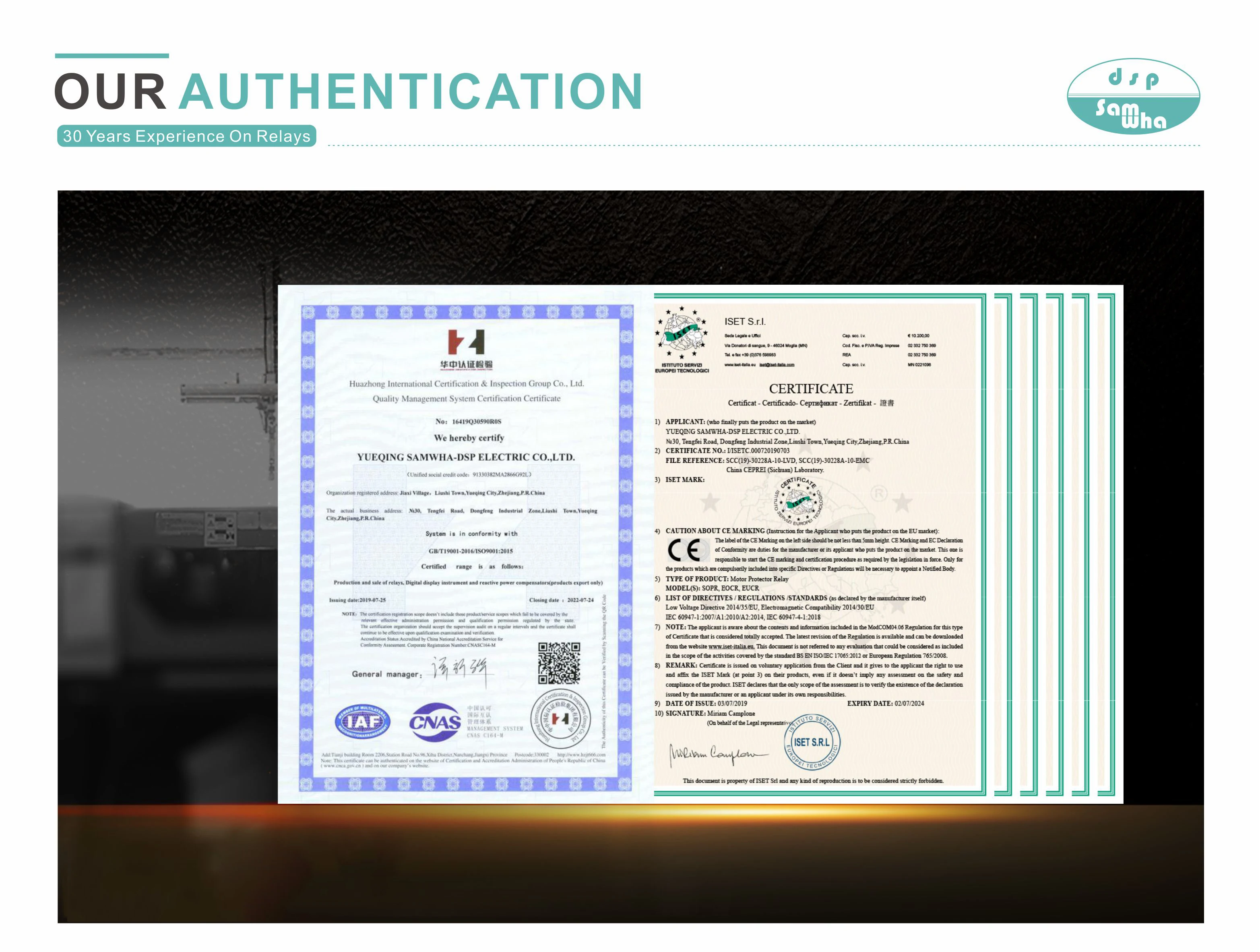
Certification: CE
DC Voltage: NONE
DIY Supplies: Electrical
Dimensions: 96*96
Display Type: Digital Display
High-concerned chemical: none
Is Smart Device: no
Model Number: EM-07
Operating Mode: Auto Range
Operating Temperature: -20℃~+55℃
Origin: Mainland China
General
EM-07 Multimeter measures the load on the system and voltage, current, apparent power minimum and maximum values, demands related to this load on the system.
Features
◈ RS485 Modbus RTU (1200 - 38400bps)
◈ 71.5 x 61.5 Custom Design Glass LCD
◈ 3-phase voltage and 3-phase current
transformer
◈ It shows that V1, V2, V3, V12, V23, V31, I1, I2,
I3, S1, S2, S3, F1, F2, F3
◈ It shows the minimum, maximum and
average values of V1, V2, V3, V12, V23, V31,
F1, F2, F3
◈ It shows the minimum, maximum, average
and demand values of I1, I2, I3, S1, S2, S3
◈ High/Low voltage, current, frequency
(adjustable)
◈ Phase-Neutral or Phase-Phase protection
(adjustable)
◈ 1x Relay output
◈ Protect Voltage, Current and Frequency
◈ Shows phase sequence
◈ Can delete the demands
◈ Menu is password-protected
Construction
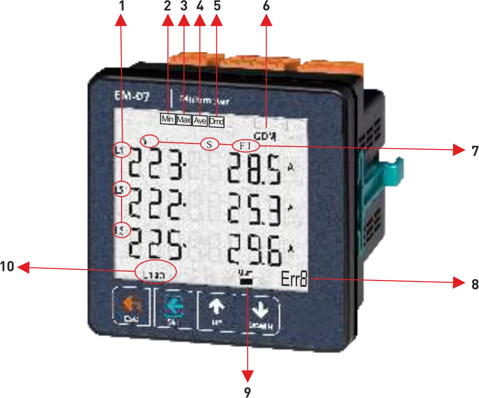
1 - It shows phase number belong to measurement values
2 - Showing values are minimum of measurement values
3 - Showing values are maximum of measurement values
4 - Showing values are average of measurement values
5 - Showing values are demand of measurement values
6 - It shows Serial Communications
7 - It shows that type of measurement values
8 - It shows number of error
9 - It shows relay state. OUT1▬ means that relay is close, OUT1 — means that relay is open
10- It shows phase sequence. "L123" means that phase sequence is correct. "L132"means that phase sequence is incorrect.
Definition of Buttons
ESC Button:
-State of Measurement; Back to home screen.
-State of Menu; Exit menu. State of changing
parameter; Not save chance and back to menu
state.
-State of Error; Manual reset
SET Button:
-State of Measurement: Entry Menu.
-State of Menu: Entry state of changing
parammeter.
-State of changing parameter: save change and
back to menu state
UP Button:
-State of Measurement: To navigate from a main
measurement values to another.
-State of Menu: To navigate from menu
parameters to another.
-State of changing parameter: Increase value of
parameter
RIGHT Button:
-State of Measurement: To navigate from a deep
measurement values to another(min,max,avg,
dmd)
-State of Menu: To navigate from menu
parameters to another
-State of changing parameter: Decrease value of
parameter
Error Codes
If device in any case of error cut off, Relay will be open, backlight of display will be turn on and bottom right-handcorner of display will display ERR Code.
Err0 = Phase Sequence Error
Err1 = High Voltage Error
Err2 = Low Voltage Error
Err3 = High Current Error
Err4 = Low Current Error
Err5= High Frequency Error
Err6= Low Frequency Error
Err7= Demurrage Error
Err8= Volage Fuses Error
Err9= Current Fuses Error
ErrA= Asymmetry Voltage Error
ErrB= Asymmetry Current Error
Warnings
▲Use the device according to the instructions specified by us.
▲Do not expose the LCD display directly to sunlight in order to avoid any harm on it.
▲Note that the temperature level on the panel to which the device is mounted is at the range ofoperating temperature of the device (-20°C.....55°C).
▲There must be a space of 5cm behind the device after its installation.
▲Fix the device securely to the front-cover of the panel with the apparatus delivered together with the device.
▲Be sure that the panel to which the device is mounted does not operate in a humid environment.
▲Place the switch or circuit breaker close to the device or in a location that is easily accessible for theoperator.
▲Place a switch or circuit breaker on the system during installation of the device.
▲Please note that the cables must not be energized during installation.
▲Flexible monitored and twisted cables must be used for the input and output lines which are notconnected to the mains.
▲The technical personnel according with the instructions specified in the user's manual must performinstallation of the device and electrical connections.
▲The feeder cables must be compatible with the requirements of lEC 60227 or lEC 60245
Start-up of the Device:
Read the warnings before the device is energized. Make sure that the device is connected according tothe connection diagram. When the device energized for the first time, the Home Screen is displayed. Enterthe current transformer ratio and the voltage transformer ratios*, if installed, on the settings menu at first.
*The EM-07-XXD and EM-07E-XXD do not require current transformer ratios
Points to take into consideration in the selection and connection of Current Transformer
Be sure that the current transformer value is higher than the maximum current drawn from the system.
In order to prevent any mistake while connecting the output terminals of the curent transformer, use cables in different colors for each phase or designate a number for each cable.
Keep the cables connected to the output terminals of the current transformer away from the high-voltage line.
In order to prevent any shake on the current transformer, fix it on the bus-bar, cable or rail.
Maintenance
Switch off the device and release from connections. Clean the trunk of device with a swab. Don’t use any conductor or chemical might damage the device.
Make sure device works after cleaning.
Specifications
Operating Voltage(Un).......: 85V - 240V AC
Operating Frequency..........: 50/60 Hz.
Operating Power..................: <10VA
Operating Temperature.....: -20°C.....+55°C
Voltage Input......................: 5V ~ 330V AC
Voltage Meas. Range..........: 5V ~ 330kV
Current Meas. Range...........: 50mA-10000A (With Standard C.T)
Voltage, Current Accuracy...:%±1
Supported Connection.........:3P4W
Current Transformer Ratio..:1,0...2000(EM-07/E)
Voltage Transformer Ratio....:1,0....999,9
Communication....:RS485 MODBUS RTU
Display....:71.5 x 61.5mm Glass LCD
Output..:2A / 250V AC(Resistive Load)
Weigh......................................:<300gr.
Protection Class..:IP41(Font Panel), IP20(Body)
Panel Hole Sizes....................:91mm x 91mm
Connection Type.................: Plug-in terminal
Cable Diameter....................: 1,5mm²
Mounting............: Mounting on panel front cover
Operating Altitude.............: <2000meter
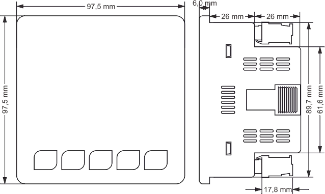
Dimensions
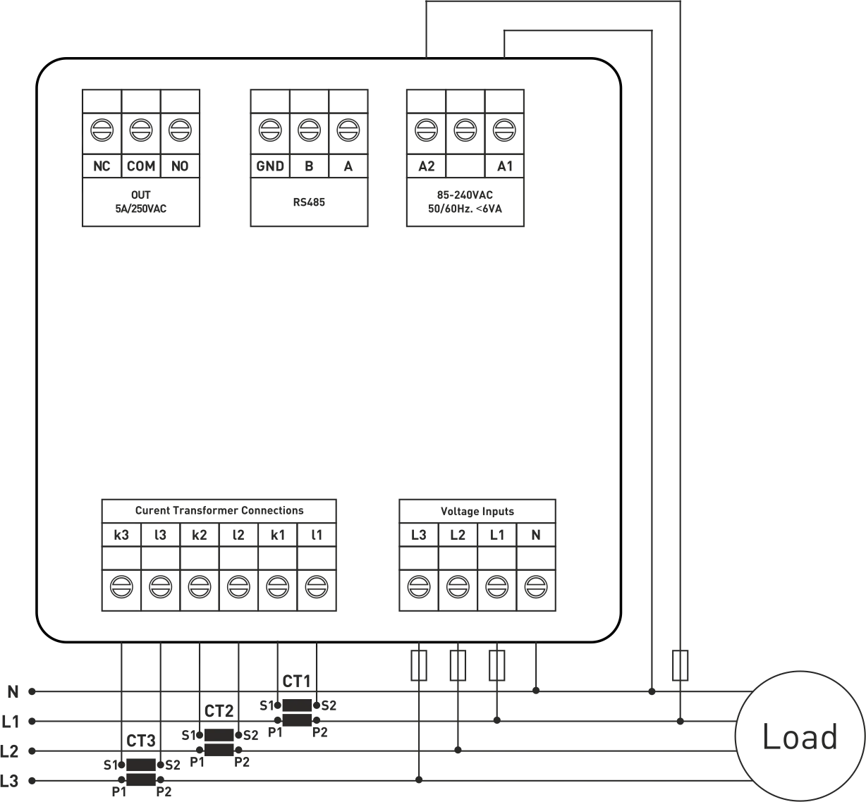
Connection Diagram
Free Shipping Over $199
- Standard Shipping: Standard Shipping (12–18 Business Days)
- Express Shipping: Expedited Shipping (5–9 Business Days)
- Free Shipping: Orders over $199 qualify automatically
- Tracking: Full tracking number provided for all orders
30-Day Return Policy
- Returns: 30-day hassle-free return window
- Condition: Items must be unused and in original packaging
- Refund: Full refund processed within 3-5 business days
Why Choose Us?
- Factory Direct: ISO/TS 16949 certified manufacturer
- Quality: 100% electrical continuity tested before shipment
- Experience: 15+ years in automotive connector industry
- Support: Professional technical support available

You may also like
Blog posts
Title
An excerpt of your blog post's content
Title
Date|Author
Subscribe to our emails
Be the first to know about new collections and special offers.