

TM1637 4 Bits/TM1638/MAX7219 8 Bit Digital LED Display Module 7 Segment 0.36Inch Clock RED Anode Tube Four Serial Driver
MAX7219
$7.52
Sale price
$7.52
Regular price
$0.00
Skip to product information


TM1637 4 Bits/TM1638/MAX7219 8 Bit Digital LED Display Module 7 Segment 0.36Inch Clock RED Anode Tube Four Serial Driver
$7.52
Sale price
$7.52
Regular price
$0.00
Description
SPECIFICATIONS
Brand Name: NoEnName_Null
Choice: yes
High-concerned chemical: none
Origin: Mainland China
is_customized: Yes
TM1637 4 Bits/TM1638/MAX7219 8 Bit Digital LED Display Module 7 Segment 0.36Inch Clock RED Anode Tube Four Serial Driver
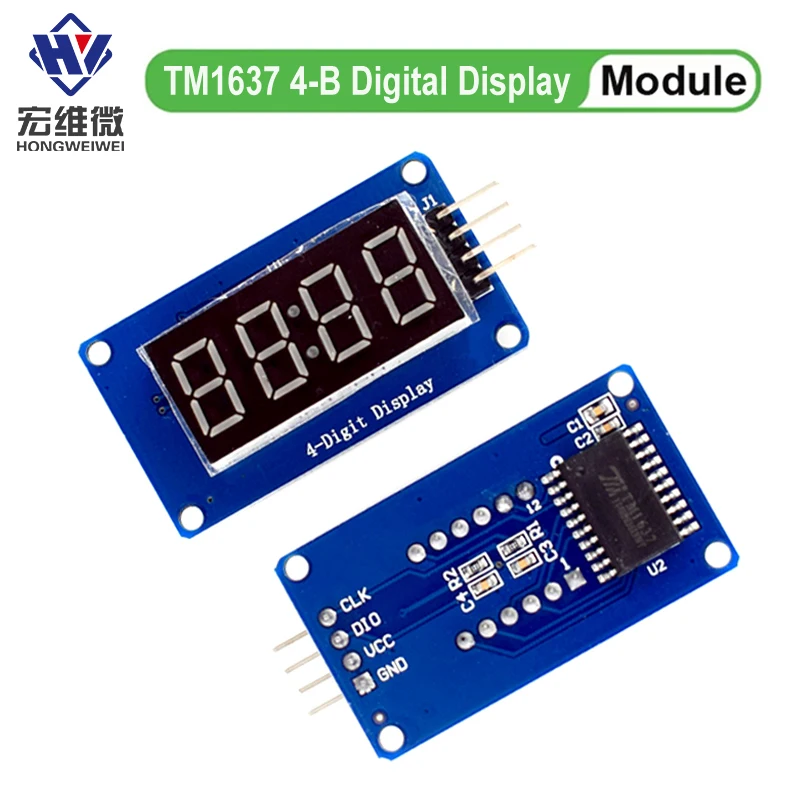
DESCRIPTION:
TM1637 is a specialized circuit for LED (Light Emitting Diode Display) driver control with keyboard scanning interface. It integrates MCU+digital interface, data latch, LED high-voltage driver, keyboard scanning and other circuits internally. Can be applied to display screen drivers for induction cookers, microwave ovens, and small household appliances.
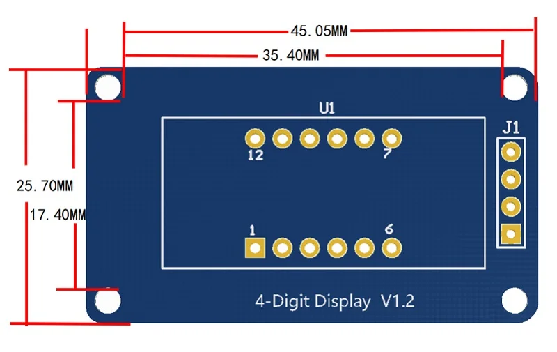
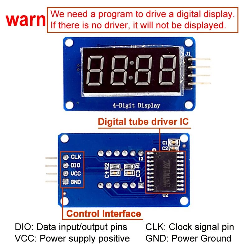
The module features are as follows:
Display device is 4-digit yang red digital tube
Digital tube 8-level grayscale adjustable
Control interface level can be 5V or 3.3V
4 M2 screw positioning holes for easy installation
Control interfaceA total of 4 pins (GND, VCC, DIO, CLK), GND is ground, VCC is the power supply, DIO is the data input and output pin, CLK is the clock signal pin;
Digital Tube: 4-digit common anode with a 0.36-inch digital tube with a score point, highlighted in red;
Positioning hole: 4 M2 screw positioning holes, the hole diameter is 2.2mm, which makes the module easy to install and position, and realize the module combination;
Overview of the library routines:
1. ClockDisplay: Use the timer 1 of the MCU on the motherboard to time and let the 4-digit display display.
2. NumberFlow: 0~9, A, b, C, d, E, F and other 16 characters flow from right to left.
3. StopWatch: Use the timer 1 of the MCU on the motherboard to time, and use the button to realize the stopwatch function.
Experiment equipment:
An Ard uino compatible motherboard Cat duino (not familiar with open source hardware can be understood as the Atmega328P microcontroller development board) and a mini USB cable;
1 4-digit digital tube display module;
4 male to female DuPont lines for connecting the control interface of the module and the Cat duino development board;
Experimental procedure:
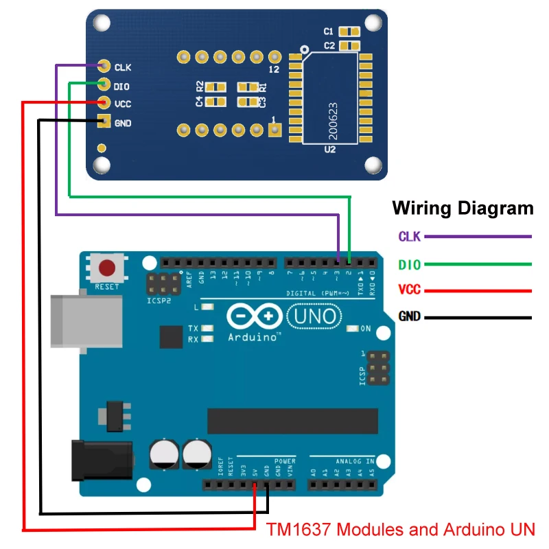
1. Use 4 male to female DuPont lines 4-digit digital display module Connected to Cat duino, as shown in the following table and figure
2. Connect the Catduino with mini USB. If you are using the motherboard for the first time, its USB to serial driver can find the USB Drivers from the drivers in the Ard uino IDE directory.
3. Reopen the Ard uino IDE and click the Open button on the toolbar to open the NumberFlow routine in DigitalTube.
Select the serial port, board name, click the Burn button, you can burn. This routine can make 16 characters from 0~9, A, b, C, d, E, F, etc. flow from right to left.
The function of adjusting the gray scale of the digital tube is the set() function in the class TM1637, and the input parameter is 0~7. The larger the number, the higher the brightness.
Description
The rated voltage: DC12V
Voltage range: DC7.0 V-13.6 V
The input power: 0.24 A
The rated speed: 9500 R.P.M
Temperature range:-10.. 70 ° C
Txpect life: 25 ° C L10 when expected life 50000 hours
Bearing structure: free maintenance dual ball bearings
Rotation direction: the wind from stents place eduction, facing the rotor counter-clockwise
The wiring way: + red-black signal: blue (blue line, the alarm line speed, it is necessary to pay attention to). Line about 20 cm long
The biggest air volume: 26.8 m? / h
The electric motor protection : overload protection, wrong level protection and stall lock current protection
Minimum wind pressure : 0.. 120 Pa
Noise index : 41.9 dB (A)
Material qualitative material: glass fiber reinforced plastic, PBT shell, PA blades
Function explain : electronic reversing the rotor dc fans, complete electronic directional control components
Including the following resources:
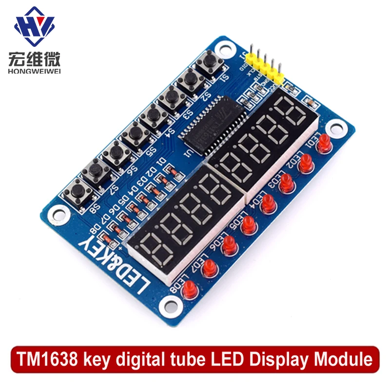
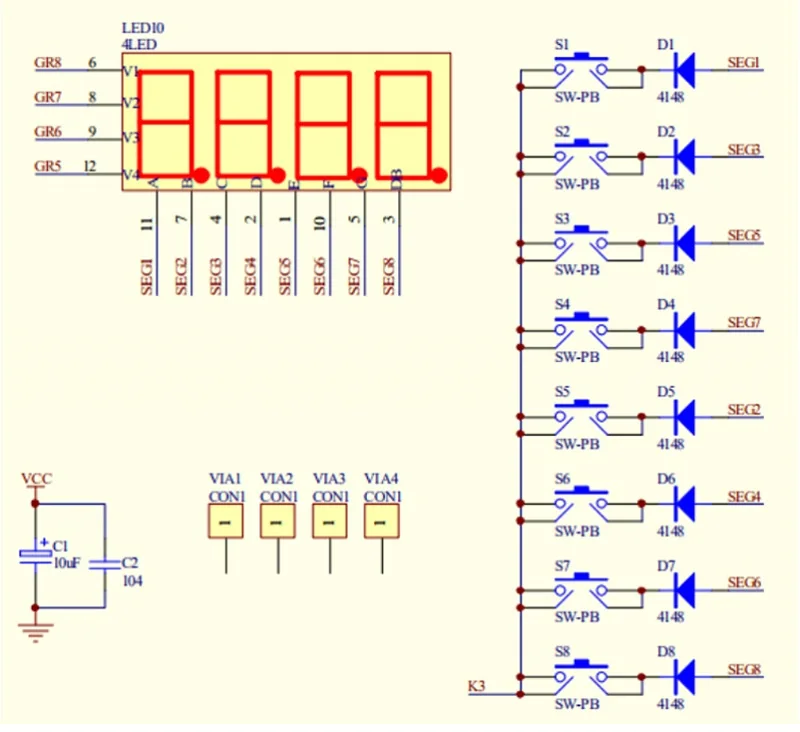
1. 8 key
2. 8 LED common cathode
3. 8 a digital tube common cathode
Use TM1638 digital tube drive chip to drive common cathode LED digital tube
How to connect:
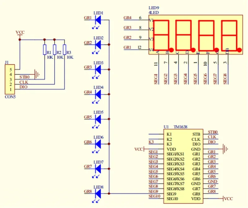
VCC GND 5V power supply, STB CLK DIO MCU I/O port
This module for the chip TM1638, set the above three kinds of single chip microcomputer common peripheral circuit, the biggest characteristic is to simply take microcontroller three IO mouth can drive, scanning display and key scan don't need microcontroller intervention, only need to register to display data related to reading and writing or testing buttons, save MCU resources.
Wiring methods :
VCC GND connected 5V supply, STB CLK DIO connected microcontroller IO port.
Introduction:
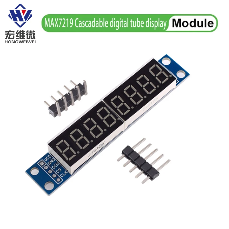
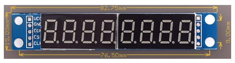
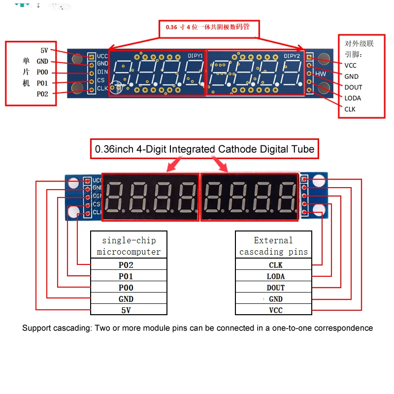
1. The display driver is MAX7219;
2. Two 0.36-inch 4-digit integrated cathode digital tubes on board;
3. Support cascading two or more modules;
4. It has 4 positioning holes with a diameter of 3.6mm;
5. Module power supply voltage DC3.3V or 5V;
6. The module is compatible with 5V/3.3V microcontrollers (STC51/AVR/STM32...)
Special Reminder:
1. Do not connect VCC and GND in reverse to avoid burning out the chip.
2.51 The PO port of the microcontroller needs to be connected to a pull-up resistor. If your microcontroller is not connected to a pull-up resistor, you can connect the data cable to another port.
Free Shipping Over $199
- Standard Shipping: Standard Shipping (12–18 Business Days)
- Express Shipping: Expedited Shipping (5–9 Business Days)
- Free Shipping: Orders over $199 qualify automatically
- Tracking: Full tracking number provided for all orders
30-Day Return Policy
- Returns: 30-day hassle-free return window
- Condition: Items must be unused and in original packaging
- Refund: Full refund processed within 3-5 business days
Why Choose Us?
- Factory Direct: ISO/TS 16949 certified manufacturer
- Quality: 100% electrical continuity tested before shipment
- Experience: 15+ years in automotive connector industry
- Support: Professional technical support available

You may also like
Blog posts
Title
An excerpt of your blog post's content
Title
Date|Author
Subscribe to our emails
Be the first to know about new collections and special offers.