

ZS-X11H/ZS-X11H V1 DC6-60V 400W BLDC three-phase DC brushless Hall motor controller motor drive module PWM signal input
ZS-X11H V1
$61.29
Sale price
$61.29
Regular price
$0.00
Skip to product information


ZS-X11H/ZS-X11H V1 DC6-60V 400W BLDC three-phase DC brushless Hall motor controller motor drive module PWM signal input
$61.29
Sale price
$61.29
Regular price
$0.00
Description
SPECIFICATIONS
Brand Name: diymore
Choice: yes
Condition: New
Dissipation Power: 400W
High-concerned chemical: none
Origin: Mainland China
Quantity: 1
Supply Voltage: DC6-60V
Type: Drive IC
ZS-X11H V1:
This driver is a DC three-phase brushless control board that requires the motor to have a Hall sensor in order to function properly
This driver is only suitable for DC brushless Hall motors with an electrical angle of 120 degrees
Newly upgraded BLDC wide voltage 6-60V high power 400W DC three-phase brushless with Hall controller, supporting PLC 0-5V analog control
Supports PWM control amplitude of 2.5-5V
Special instructions for external signal input:
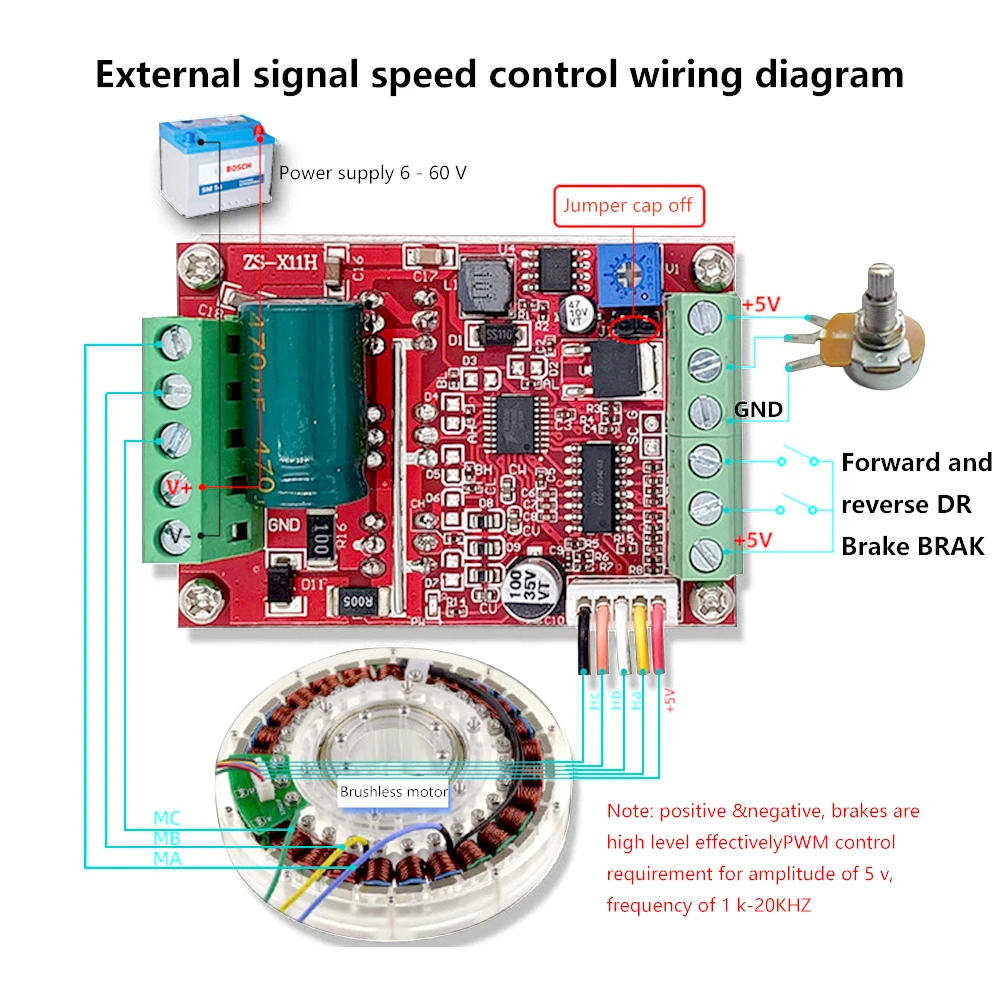
When connecting PWM signal input from the two ports of the motherboard P G (with the built-in potentiometer on the board set to the minimum, and short circuiting the short interface wiring on the board as shown in the diagram above), the amplitude is 2.5-5V and the frequency is 50HZ-20KHZ.
2. When external analog input is 0-5V, input from the two terminal ports on the motherboard (the built-in potentiometer on the board is adjusted to the minimum, and the wiring is illustrated by the dashed line in the diagram above)
3. When using an external potentiometer for speed regulation, connect the corresponding three terminal ports on the motherboard (adjust the potentiometer on the board to the minimum, and follow the potentiometer diagram for wiring)
4. Forward and reverse rotation, as well as stopping, can be achieved by grounding a switch (0 potential) to a low level, or by receiving a low level signal from an external MCU. The brake switch is connected to a 5V high level effective front row of wiring terminals, all of which are weak current signals directly input to the MCU main control, and cannot touch or come into contact with high voltage and strong current.
Interface Description:
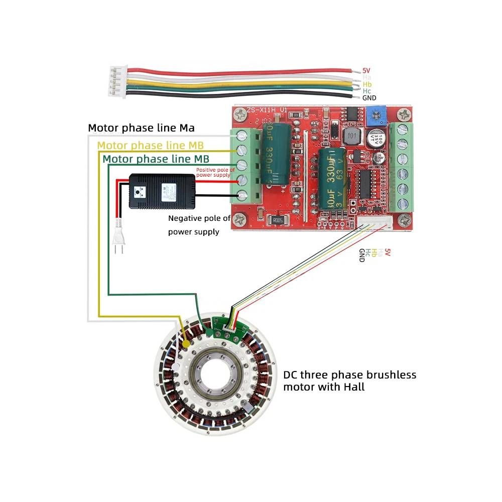
1. MA MB MC phase line output connected to motor
2. The 5V GND motherboard comes with a 5V power supply (which can provide external power with a current not exceeding 50mA)
3. VCC GND main power supply (external DC power supply)
4. SC speed pulse signal output (leaving only interface, no technical support)
5DIR direction control forward and reverse control interface (effective low level can be connected to an external switch)
6STOP stop control interface (low level valid for external grounding switch)
7BRAKE brake control brake control interface (high level valid for 5V external switch)
8. Speed control speed signal input (integrated potentiometer speed control on the board can also be externally connected with 0-5V analog PWM dual signal input speed control)
9. Ha Hb Hc+5V GND Hall signal power input interface, generally motors with Hall have corresponding 5 wires
After upgrading the SMT process, the performance is stable with a forward and reverse stop brake function
Debugging instructions: Please read and understand before powering on the machine for testing. It is very important, very important!!!
After receiving the driver board, first check if the interface can correspond to your brushless motor interface.
1. Generally, there are 5 Hall wires or interfaces on a brushless motor, of which 2 are Hall power supply wires and 3 are Hall signal wires. It is important to distinguish between them, especially the Hall power supply wires (which are usually marked with red and black wires, but there are also some that are not, and it is unclear how to find a solution from the motor manufacturer). Do not make mistakes. The three Hall signal wires are usually marked with a, b, c, and the drive board also has three ports such as ha, Hb, Hc, etc., which should be connected correspondingly
2. There are three relatively thick phase lines on the motor, and there are also three phase line interfaces on the drive board. They are marked with characters such as MA, MB, MC, etc., and are connected accordingly. After confirming that they are correct, the main power supply can work normally. (If the interfaces are correctly labeled and cannot function properly even when powered on, it cannot be ruled out that there may be non-standard manufacturer labeling or other reasons. Please debug according to the following 3 unclear interface definitions.)
3. If you are not clear about the definitions of motor phase lines and Hall lines, you can connect the three phase lines of the motor to the interface of the drive phase lines at will, and at the same time, connect the three signal lines of the Hall lines to the Hall interface on the drive board at will (but the two Hall power supply lines must be found and connected correctly, remember!!!). Then, during the first power on, adjust the low voltage and low current (if possible, use a constant current power supply to adjust the voltage to 7-12V and the current to 1-2A), and then switch the three Hall lines in any order (switch any two of the motor's three Hall signal lines to the drive Hall interface, and test every time you switch them) until they can rotate smoothly after power on, which indicates that the wiring is connected. Correct, there are 6 combinations of wiring, please refer to the following picture
True value table of motor phase line and Hall signal line
The phase lines of the MA, MB, and MC motors can be connected without moving, and only the Hall signal line can be adjusted
Corresponding Hall phase sequence connection method:
1 ha hb hc
2 hc ha hb
3 hb hc ha
4 ha hc hb
5 hb ha hc
6 hc hb ha
There are 6 combination wiring methods above, 1 is correct, 2 and 3 motors may rotate in the same direction
Moving in another direction will not turn, while the other three types of motors will not turn
4. When the wiring is incorrect, do not use high current or high voltage debugging, otherwise there is a risk of damaging the drive board. If the three Hall signal wires are swapped and connected correctly, the motor will run smoothly and smoothly at low speeds after power on, with large torque; If the three Hall signal lines are not connected in a corresponding sequence, there are generally the following
characteristics:
1. After being powered on, the motor cannot start normally without any response or only shakes briefly during startup and cannot rotate normally
2. It has slight shaking and difficulty starting, sometimes requiring manual operation to start
3. The motor can rotate in one direction, but cannot rotate in the other direction, and some may have a slight shower noise
4. The motor starts with large shaking and weak power, and there is a bath sound. The high-power tube is significantly overheating.
Humanized design, the interface adopts terminal posts and comes with standard heat sinks. The integrated speed control potentiometer on the board can be used by hand, saving time and effort
Motherboard specifications:
Product Name: 400W Brushless Hall DC Motor Driver
model: ZS-X11H V1
Working voltage: 6-60V
Maximum current: rated 16A peak 20A
Maximum power: 400W
Overcurrent protection: Yes
Product dimensions: length 63MM * width 45MM * height 31MM
Weight: Approximately 77g
matters needing attention:
1. There is no fuse in the power supply circuit on the motherboard, so it should be added by oneself. Reversing the positive and negative poles of the power supply can cause permanent damage to some chips on the board (even for a few seconds under high current)
2. During normal operation, the motor output terminal is equipped with sampling overcurrent protection. Due to the high power and current of the module, please do not artificially short circuit it when the module is not working properly. Once short circuited, there is a possibility of burning the circuit and bursting the tube. For the first wiring test, please use a low current and low voltage test. After it is OK, then apply a high current and high voltage. As it is a bare board module, please pay attention to the insulation of the wiring head and strictly prohibit strong voltage from touching the parts on the board
3. Do not connect motors that do not match or differ significantly from the voltage, current, and power of the drive module to avoid inexplicable damage
Product List:
1X module
1 X-ray

ZS-X11H:
Product features:
1. The product is made of high-quality materials with guaranteed quality
2. The product has stable performance, with a maximum power of up to 400W and a long service life
3. The product is suitable for car, household, industrial equipment, DIY enthusiasts, etc
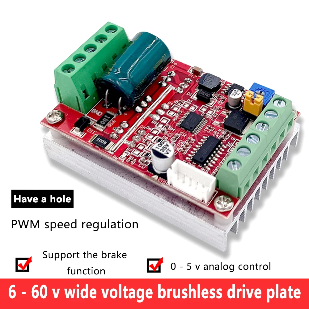
4. This is a Hall wide voltage brushless drive board that supports wide voltage DC6-60V, brake function, and 0-5V analog speed regulation
5. Equipped with forward and reverse control function, PWM duty cycle control for speed regulation
Module Introduction:
This is a BLDC wide voltage DC6-60V, high-power 400W three-phase DC brushless with Hall motor controller, newly added PLC, 0-5V analog control speed regulation and braking function, forward and reverse control, PWM duty cycle control speed regulation. The product is suitable for DC brushless Hall motors with an electrical angle of 120 degrees.
Product parameters:
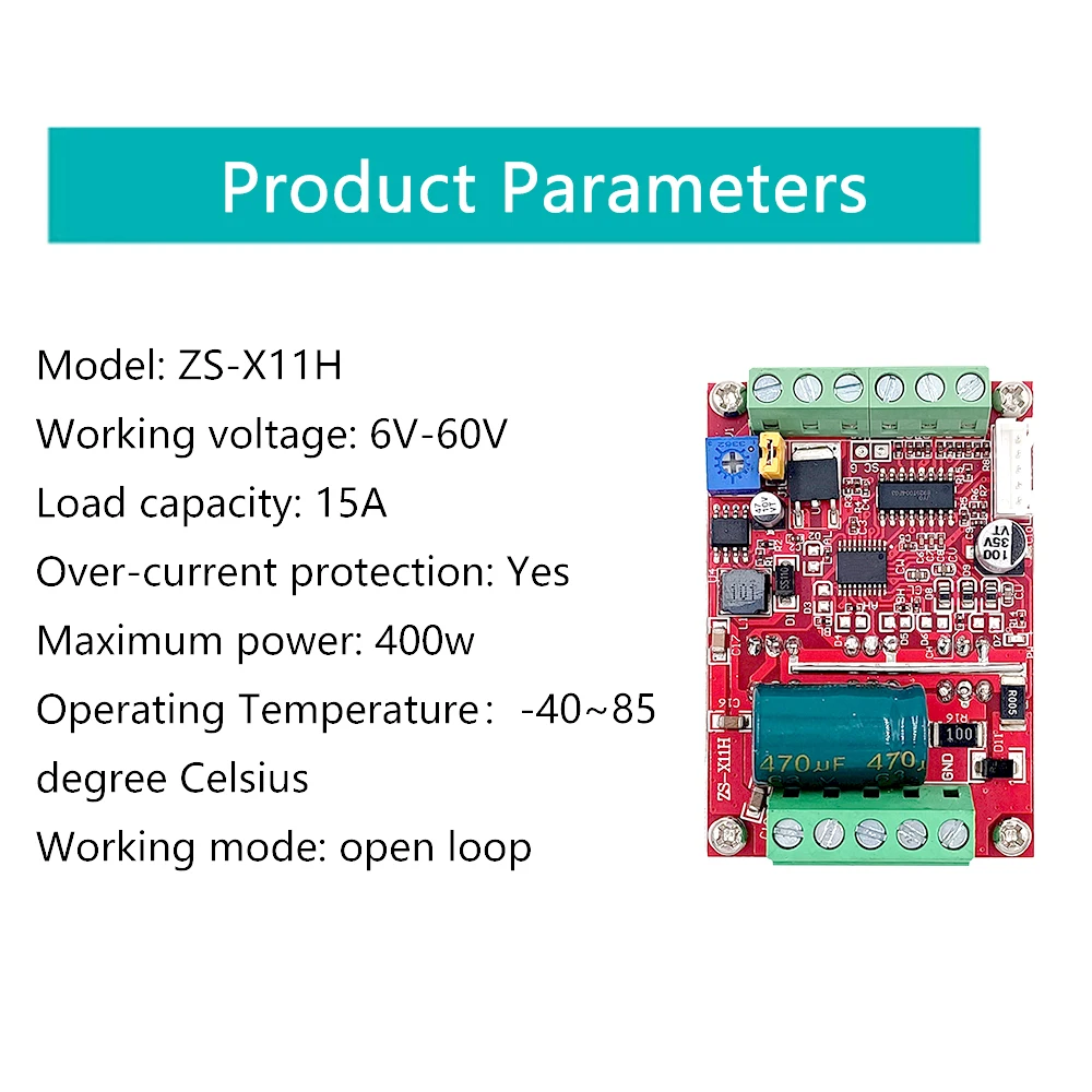
model: ZS-X11H
Working voltage: 6V-60V
Load capacity: 15A
Overcurrent protection: Yes
Maximum power: 400w
Working environment temperature: -40~85 degrees Celsius
Working mode: open-loop
matters needing attention:
1. There is no fuse in the power supply circuit on the motherboard, so it should be added by oneself. Reversing the positive and negative poles of the power supply can cause permanent damage to some chips on the board (even for 2 seconds)
2. During normal operation, the motor output terminal has overcurrent protection. Due to the high power and current of the module, please do not artificially short circuit it when the module is not working properly. Once the short circuit occurs, there is a possibility of burning the circuit and bursting the tube. For the first wiring test, please use a low current and low voltage test. After it is OK, then apply a high current and high voltage. As it is a bare board module, please pay attention to the insulation of the wiring terminals and strictly prohibit strong voltage from touching the parts on the board
3. Do not connect motors that do not match or differ significantly from the voltage, current, and power of the drive module to avoid damage
4. Carefully check the wiring before powering on, reverse connection or incorrect connection of Hall wire, sudden high current is likely to burn out the drive board
5. If the motor cannot start normally or has difficulty starting (sometimes it needs to be manually turned to start), the wiring phase may be incorrect. Please cut off the power immediately, otherwise it is easy to damage the drive instantly
Shipping List:
Module X1
5PIN wire X1

Free Shipping Over $199
- Standard Shipping: Standard Shipping (12–18 Business Days)
- Express Shipping: Expedited Shipping (5–9 Business Days)
- Free Shipping: Orders over $199 qualify automatically
- Tracking: Full tracking number provided for all orders
30-Day Return Policy
- Returns: 30-day hassle-free return window
- Condition: Items must be unused and in original packaging
- Refund: Full refund processed within 3-5 business days
Why Choose Us?
- Factory Direct: ISO/TS 16949 certified manufacturer
- Quality: 100% electrical continuity tested before shipment
- Experience: 15+ years in automotive connector industry
- Support: Professional technical support available

You may also like
Blog posts
Title
An excerpt of your blog post's content
Title
Date|Author
Subscribe to our emails
Be the first to know about new collections and special offers.