

ZY MPU9250 9-Axis Gyroscope Sensor Module Accelerometer Magnetometer Attitude Detection I2C Communication
China Mainland
$64.31
Sale price
$64.31
Regular price
$0.00
Skip to product information


ZY MPU9250 9-Axis Gyroscope Sensor Module Accelerometer Magnetometer Attitude Detection I2C Communication
$64.31
Sale price
$64.31
Regular price
$0.00
Description
SPECIFICATIONS
Brand Name: ICGOICIC
High-concerned chemical: none
Origin: Mainland China
Use: MAGNETIC SENSOR
is_customized: Yes
1. Product introduction:
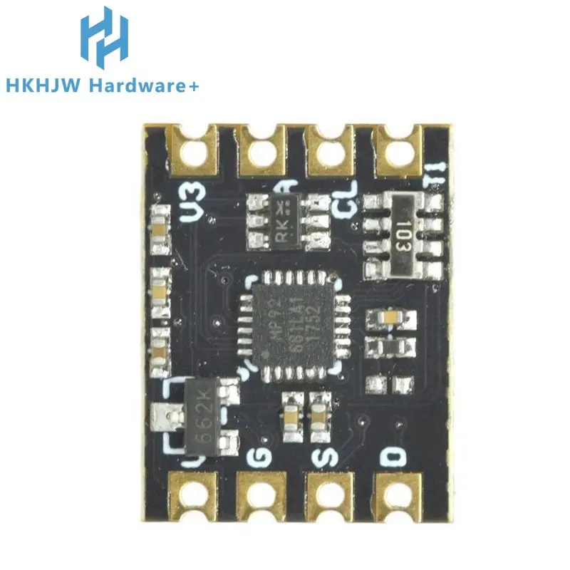
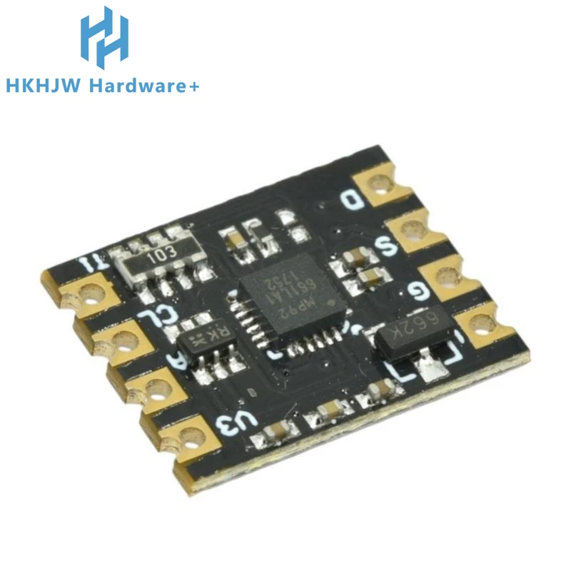
M with PU3250 accelerometer magnetometer module is based on MPU9250 nine-axis motion processing chip integrated with peripheral DO, I2C pull-up resistance module, expanded to double rows of 2.54mm spacing gold-plated pinholes and stamp holes, easy for users to weld and expand, can also be directly affixed to users' products, the module adopts I2c communication, Support wide operating voltage. Use braided packing.
The MPU9250 chip is integrated with 3-axis gyroscope, 3-axis acceleration and 3-axis magnetometer sensors. Three 16-bit ADCs are used to convert the measured analog quantity into the output digital quantity for the butterfly meter, accelerometer and magnetometer respectively. To accurately track fast and slow motion, the sensor has a user controlled measurement range of ±250, ±500, ±1000, ±2000°/ second (dps) for the gyroscope, ±2, ±4, ±8, ±16g for the magnetometer, ±4800uT.
The MPU9250 chip also has a second IIC interface, which can be used to connect to the external magnetic sensor. Using the built-in digital motion processor < DMP > hardware acceleration engine, through the main IIc interface, the application side can output the complete 12-axis fusion calculation data. With DMg, we can use the official motion processing driver library, very convenient to achieve attitude calculation, reduce the load of motion processing operation on the operating system, and greatly reduce the difficulty of development.
2. Main parameter:
Working voltage :3.ov~5.5v
IIC communication interface, support the maximum 400Khz communication rate
acceleration measurement range :±21 soil 4/ 8/ soil 16g
gyro measuring range :±250/ 500f 1000s 2000°{s
magnetometer measuring range :±4800uT
Resolution: Acceleration :16384LSB/g(Max) Gyroscope :131LSB/(°/s)(Maxz), magnetometer :14 bit (0.6HTLSB) or 16 bit (15PTASa)
output rate: acceleration :1Khz (Max) Gyroscope :8Khz (Max)
Attitude solution output rate 200Hz (Max)
the temperature sensor measurement range :-40℃ 85℃, accuracy ±1℃
3. Foot position description:
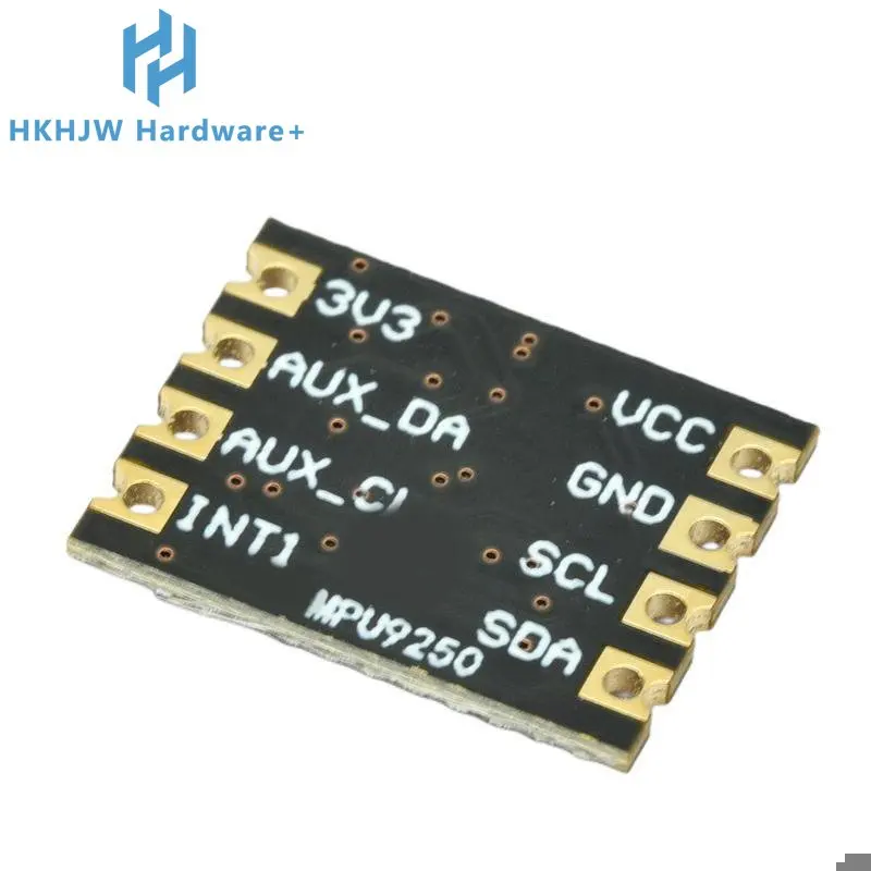
VCC: Power input
GND: electrically
SCL: Working 2C clock, inner 10K pull-up
SDA: Work 2c data, built-in 10K pull-up
INT: Interrupt output pin
AUX_CL: As the host I2C clock interface, connected to the sCL of the external sensor
AUX_DA: As the host I2c data interface, connected to the SDA of the external sensor
3V3: 3.3V voltage output
4. Application field:
(1) Handheld instrument
(2) Robot navigation and positioning
(3) Navigation model system (4) balancing vehicle
(5) Antenna pitch positioning
5. Chip pin and coordinate direction:
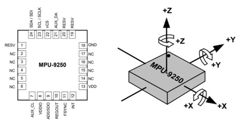
6. Function introduction:
This module reads data through I2C interface. The I2c device address is b110100K and the length is 7 bits. The last bit X of the 7-bit address is determined by the high and low level of the pin Ano pin. The default ADO dropdown grounding address is b1101000. If ADo is connected to 3.3v and configured as high level, then the rac device address is b1101001 and the length is 7 bits. The Ao connection 3.3v setting can be set by short welding spot on the module.
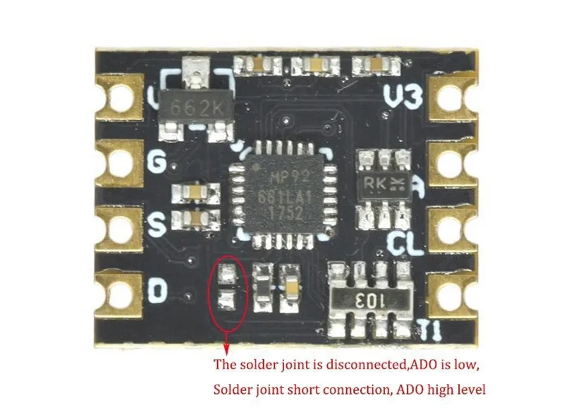
Through the data fusion and calculation of M-equipped U9250 gyroscope, accelerometer and magnetometer, the dip angles of x, y and z axes of objects (such as quadcopter and balancing car) can be obtained: Pitch, roll Angle Rol1, Yaw. Nine data of MPU9250 < AD value of triaxial acceleration, AD value of triaxial angular velocity and sD value of triaxial magnetometer > can be read through T2. After attitude fusion, Pitch, Ro11 and Yaw angles can be obtained.
As the direction reference of the measured value, the sensor coordinate direction is defined as shown in the figure above, which belongs to the right-handed coordinate system < right thumb points to the positive direction of x axis, index finger points to the positive direction of y axis, and middle finger can point to the positive direction of z axis ".
Note: In order to obtain more stable output, it is necessary to calibrate data < zero offset > and filter < common filters include complementary filter, Kalman filter, etc.).
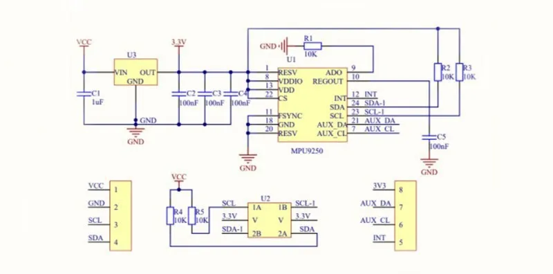
7. Application schematic diagram:
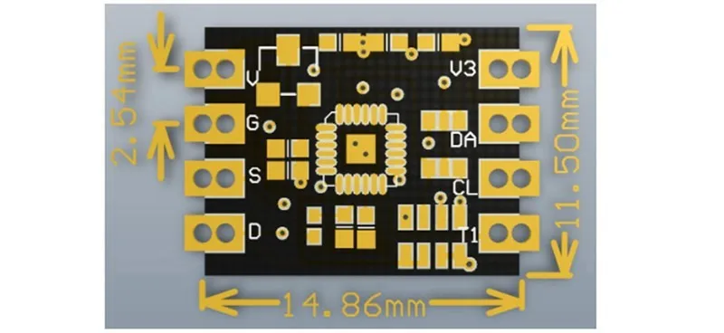
8.Product size:
Free Shipping Over $199
- Standard Shipping: Standard Shipping (12–18 Business Days)
- Express Shipping: Expedited Shipping (5–9 Business Days)
- Free Shipping: Orders over $199 qualify automatically
- Tracking: Full tracking number provided for all orders
30-Day Return Policy
- Returns: 30-day hassle-free return window
- Condition: Items must be unused and in original packaging
- Refund: Full refund processed within 3-5 business days
Why Choose Us?
- Factory Direct: ISO/TS 16949 certified manufacturer
- Quality: 100% electrical continuity tested before shipment
- Experience: 15+ years in automotive connector industry
- Support: Professional technical support available

You may also like
Blog posts
Title
An excerpt of your blog post's content
Title
Date|Author
Subscribe to our emails
Be the first to know about new collections and special offers.