

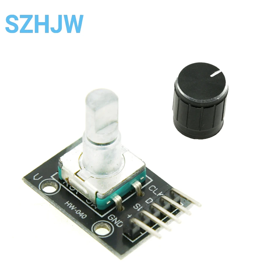
1-50PCS KY-040 Rotary Encoder Module – 20 PPR, 360° Infinite Rotation with Push Button, for Arduino Raspberry Pi
KY-040 / 5PCS
$24.12
Sale price
$24.12
Regular price
$0.00
Skip to product information


1-50PCS KY-040 Rotary Encoder Module – 20 PPR, 360° Infinite Rotation with Push Button, for Arduino Raspberry Pi
$24.12
Sale price
$24.12
Regular price
$0.00
Description
SPECIFICATIONS
Application: Other
Brand Name: SZYTF
Choice: yes
Condition: New
Dissipation Power: N/A
High-concerned chemical: none
Operating Temperature: .
Origin: Mainland China
Package: Other
Supply Voltage: 5V
Type: Other
is_customized: Yes
semi_Choice: yes
Operating voltage: 5V
Pulse count in one turn: 20
The rotary encoder can count the number of output pulses in the forward direction and the reverse direction by rotation. Unlike the potentiometer, the rotation count is unlimited. With the key on the rotary encoder, it can be reset to the initial state, that is, counting from 0.
Working principle:
Incremental encoder is a rotary sensor that converts rotating displacement into a series of digital pulse signals. These pulses are used to control angular displacement. The angular displacement conversion in Eltra encoder is based on photoelectric scanning principle. The READING SYSTEM IS BASED ON THE ROTATION OF A RADIAL DIAL (CODE DIAL) CONSISTING OF ALTERNATING LIGHT AND OPAQUE Windows, SIMULTANEOUSLY ILLUMINATED VERTICALLY BY AN INFRARED LIGHT SOURCE, WHICH PROJECTS THE IMAGE OF THE CODE DIAL ONTO THE RECEIVER SURFACE. The receiver is covered with a diffraction grating, which has the same window width as the code plate. The receiver's job is to sense the changes caused by the rotation of the disc and then convert the optical changes into corresponding electrical changes. The low level signal is then raised to the high level to produce a square pulse without any interference, which must be processed by electronic circuits. The readout system is usually differential, in which two different signals with the same waveform but a phase difference of 180° are compared to improve the quality and stability of the output signal. The reading is based on the difference between the other two signals, thus eliminating interference.
Incremental encoder:
The incremental encoder gives two phase square waves with A phase difference of 90°, commonly referred to as A channel and B channel. One of the channels gives information related to the rotation speed, and at the same time, the information of the rotation direction is obtained by sequential comparison of the signals of the two channels. There is also A special signal called Z or zero channel, which gives the zero bit of the encoder. This signal is a square wave that coincides with the center line of the square wave in channel A.
Incremental encoder accuracy depends on both mechanical and electrical factors, such as grating indexing errors, disc eccentricity, bearing eccentricity, errors introduced by electronic reading devices, and optical inaccuracies. The measurement unit to determine the encoder accuracy is the electrical degree, and the encoder accuracy determines the pulse degree produced by the encoder. In the following, 360° electrical degrees are used to represent the rotation of the mechanical shaft, and the rotation of the shaft must be a complete cycle. To find out how many mechanical angles are equivalent to an electrical 360 degrees, use the following formula: electrical 360 = mechanical 360°/n° pulse/revolution
Figure: Signal of A and B reversing
The encoder indexing error is expressed as the offset of two consecutive pulse waves in electrical Angle. Error exists in any encoder, which is caused by the foregoing factors. The Eltra encoder has an error of ±25 electrical angles (under any condition stated), which corresponds to a rating offset of ±7%, and a deviation of ±35 for two channels with a phase difference of 90° (electrically). The electrical degree corresponds to a rating offset of about ±10%.
UVW signal incremental encoder
In addition to the above traditional encoders, some are incremental encoders integrated with other electrical output signals. An example is the incremental encoder integrated with the UVW signal, which is commonly used for AC servo motor feedback. These magnetic pole signals generally appear in AC servo motors, and UVW signals are generally designed by simulating the function of magnetic components. In the Eltra encoder, these UVW signals are generated optically and appear as three square waves, which are offset 120° from each other. These correct signals are required for the starter to control the motor for easy starting. These UVW pole pulses can be repeated many times in a mechanical shaft rotation because they depend directly on the number of motor poles connected and are used for UVW signals for 4, 6 or more pole motors.
******************
test code:
const int interruptA = 0; / / Interrupt 0 (pin 2)
const int interruptB = 1; / / Interrupt 1 (pin 3)
int CLK = 2; / / PIN2
int DAT = 3; / / PIN3
int BUTTON = 4; / / PIN4
int LED1 = 5; / / PIN5
int LED2 = 6; / / PIN6
int COUNT = 0;
void setup ()
{
attachInterrupt (interruptA, RoteStateChanged, FALLING);
/ / AttachInterrupt (interruptB, buttonState, FALLING);
pinMode (CLK, INPUT);
digitalWrite (2, HIGH); / / Pull High Restance
pinMode (DAT, INPUT);
digitalWrite (3, HIGH); / / Pull High Restance
pinMode (BUTTON, INPUT);
digitalWrite (4, HIGH); / / Pull High Restance
pinMode (LED1, OUTPUT);
pinMode (LED2, OUTPUT);
Serial.begin (9600);
}
void loop ()
{
if (! (digitalRead (BUTTON)))
{
COUNT = 0;
Serial.println ("STOP COUNT = 0");
digitalWrite (LED1, LOW);
digitalWrite (LED2, LOW);
delay (2000);
}
Serial.println (COUNT);
}
/ / -------------------------------------------
void RoteStateChanged () / / When CLK FALLING READ DAT
{
if (digitalRead (DAT)) / / When DAT = HIGH IS FORWARD
{
COUNT;
digitalWrite (LED1, HIGH);
digitalWrite (LED2, LOW);
delay (20);
}
else / / When DAT = LOW IS BackRote
{
COUNT -;
digitalWrite (LED2, HIGH);
digitalWrite (LED1, LOW);
delay (20);
}
}
Free Shipping Over $199
- Standard Shipping: Standard Shipping (12–18 Business Days)
- Express Shipping: Expedited Shipping (5–9 Business Days)
- Free Shipping: Orders over $199 qualify automatically
- Tracking: Full tracking number provided for all orders
30-Day Return Policy
- Returns: 30-day hassle-free return window
- Condition: Items must be unused and in original packaging
- Refund: Full refund processed within 3-5 business days
Why Choose Us?
- Factory Direct: ISO/TS 16949 certified manufacturer
- Quality: 100% electrical continuity tested before shipment
- Experience: 15+ years in automotive connector industry
- Support: Professional technical support available

You may also like
Blog posts
Title
An excerpt of your blog post's content
Title
Date|Author
Subscribe to our emails
Be the first to know about new collections and special offers.