

16DI/16RO 16-channel Digital Isolated Input and 16-channel Relay Isolated Output RS485 MODBUS Module with Network Disconnection
Default Title
$260.64
Sale price
$260.64
Regular price
$0.00
Skip to product information


16DI/16RO 16-channel Digital Isolated Input and 16-channel Relay Isolated Output RS485 MODBUS Module with Network Disconnection
$260.64
Sale price
$260.64
Regular price
$0.00
Description
SPECIFICATIONS
Brand Name: OMDAZZ
Condition: New
High-concerned chemical: none
Origin: Mainland China
Type: Voltage Regulator
16DI/16RO 16-channel Digital Isolated Input and 16-channel Relay Isolated Output RS485 MODBUS Module with Network Disconnection Protection
1. Product Overview
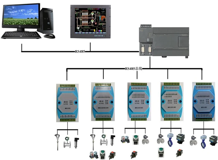
The MBSL16DI16RO module is a 16-channel digital isolated input and 16-channel relay isolated output module, which is output through an isolated RS485 interface.
1) The module adopts RS485 MODBUS RTU standard communication, it can be networked with the host computer configuration software, PLC, industrial touch screen, etc. And with communication status indicator.
2) The module complies with industrial grade standards. Signal control, power supply, RS485 communication electrical signals are all isolated from each other.
3) The communication circuit of the module adopts lightning protection, anti-interference design and power polarity protection.
4) RS485 communication signal output interface adopts over-voltage and over-current double protection.
5) This module reserves the output disconnection protection function. When the module slave station detects that the master station has not sent data beyond the set time, it will automatically reset the output to protect the safety of the field device. (This function is not available by default and can be set by software)
6) The communication format of this module can be set by software.
2. Main technical parameters
Item |
Parameter |
|
Signal input / output |
1) Input channel: 16-channel digital inputs 2) Output channel: 16-channel relay outputs 3) Load capacity: resistive load 5A / channel |
|
Communication output |
1. Communication protocol: MODBUS-RTU 2. Interface type: isolated RS485 communication, output interface has over-voltage and over-current dual protection design. 3. Baud rate: 4800bps, 9600bps, 19200bps, 38400bps, 57600bps, 115200bps 4. Check digit: no check, even check, odd check 5. Setting method: module address, baud rate and parity can be set by software 6. Communication distance: @ 9600bps 1200 meters |
Module size and installation method |
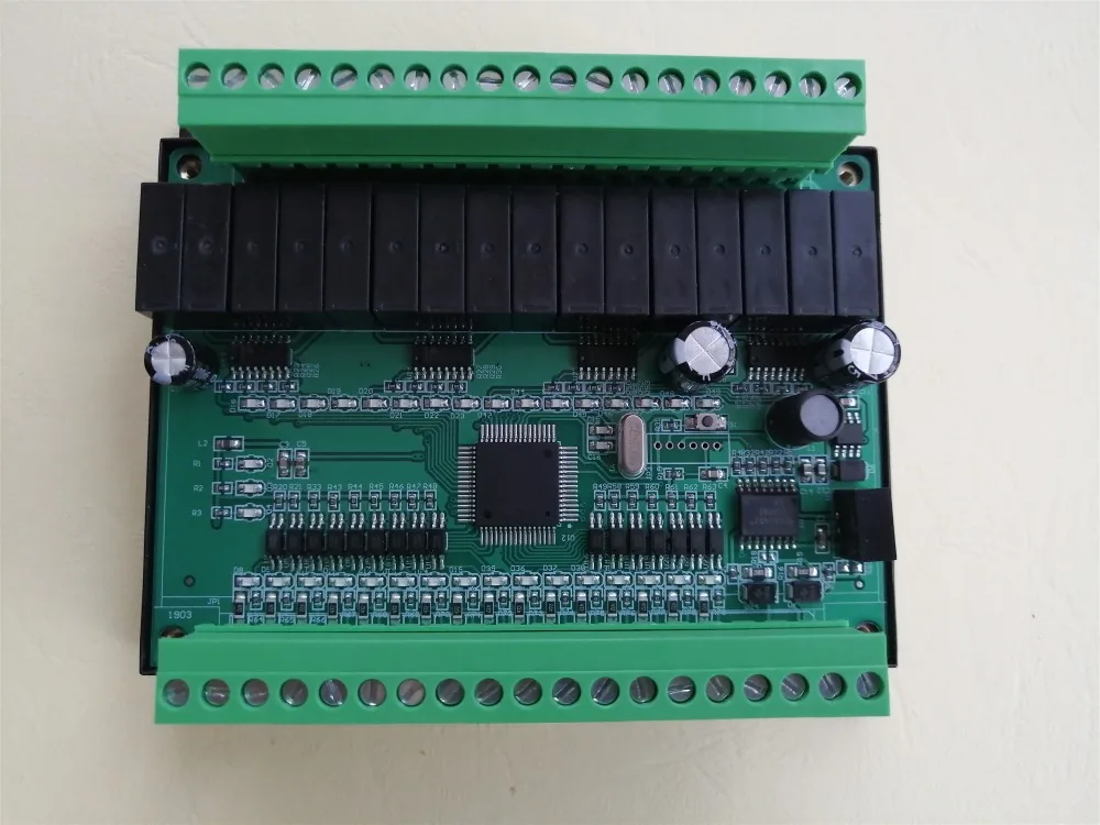
1. Installation method: Use standard DIN rail to install or use screw to install the module 2. Dimensions: 125 × 90 × 43mm |
Working environment |
Temperature: -10 ~ + 60 ℃ Humidity: 35% to 85% (no condensation) |
Working power |
1. Power supply voltage: DC24V power supply. This module is designed with power polarity protection 2. Power consumption: less than 5W |
3 The interface definition
Terminal name |
Explanation |
Terminal name |
Explanation |
PW+ |
Positive input of external power supply |
485A |
RS485 signal A+ |
PW- |
Negative terminal of external power input |
485B |
RS485 signal B- |
DI1 |
Digital input channel 1 |
DO1 |
Digital output channel 1 |
DI2 |
Digital input channel 2 |
DO2 |
Digital output channel 2 |
DI3 |
Digital input channel 3 |
DO3 |
Digital output channel 3 |
DI4 |
Digital input channel 4 |
DO4 |
Digital output channel 4 |
DI5 |
Digital input channel 5 |
DO5 |
Digital output channel 5 |
DI6 |
Digital input channel 6 |
DO6 |
Digital output channel 6 |
DI7 |
Digital input channel 7 |
DO7 |
Digital output channel 7 |
DI8 |
Digital input channel 8 |
DO8 |
Digital output channel 8 |
DI9 |
Digital input channel 9 |
DO9 |
Digital output channel 9 |
DI10 |
Digital input channel 10 |
D10 |
Digital output channel 10 |
DI11 |
Digital input channel 11 |
D11 |
Digital output channel 11 |
DI12 |
Digital input channel 12 |
D12 |
Digital output channel 12 |
DI13 |
Digital input channel 13 |
D13 |
Digital output channel 13 |
DI14 |
Digital input channel 14 |
D14 |
Digital output channel 14 |
DI15 |
Digital input channel 15 |
D15 |
Digital output channel 15 |
DI16 |
Digital input channel 16 |
D16 |
Digital output channel 16 |
COM |
Input common |
COM |
Output common |
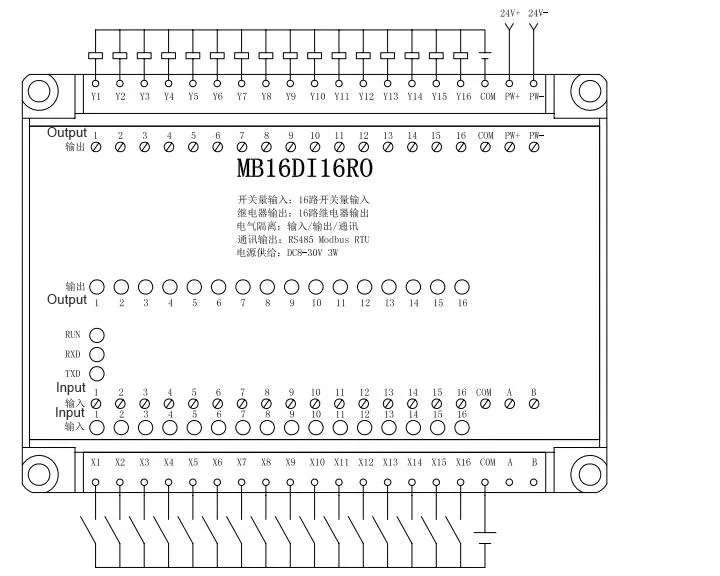
4 Module wiring diagram
5 Communication Instructions
1) Description of communication parameters (factory value): 9600,N,8,1
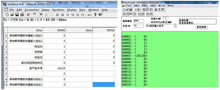
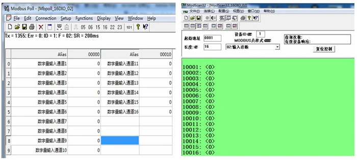
Description of Modbus register and communication protocol
1 MODBUS function code and address range supported by the module
MODBUS function codes supported by the module
Register type |
Address range |
Function code |
Description of the function code |
Operating |
Output coil register |
00001-000016 |
0x01H |
Read multiple coil registers |
Read the value of one or more coil registers |
0x05H |
Write a coil register |
Write a coil register value |
||
0x0FH |
Write one or more coil registers |
Write the value of one or more coil registers |
||
Holding register |
40001-40016 |
0x03H |
Read multiple holding registers |
Read the value of one or more holding registers |
0x 06H |
Write a single holding register |
Write a data to holding register |
||
0x 10H |
Write multiple holding registers |
Write one or more data to holding register |
||
Input digital quantity |
10001-100016 |
0x02H |
Read input discrete |
Discrete input register |
2 Register definition description
1) Output coil register (function code:0x01H、0x05H、0x0FH)
Address |
Parameter |
Length |
Read/Write |
MIN |
MAX |
Description |
00001 |
DO1 |
1 |
Read/Write |
0 |
1 |
Status of digital output bit 1 |
00002 |
DO2 |
1 |
Read/Write |
0 |
1 |
Status of digital output bit 2 |
00003 |
DO3 |
1 |
Read/Write |
0 |
1 |
Status of digital output bit 3 |
00004 |
DO4 |
1 |
Read/Write |
0 |
1 |
Status of digital output bit 4 |
00005 |
DO5 |
1 |
Read/Write |
0 |
1 |
Status of digital output bit 5 |
00006 |
DO6 |
1 |
Read/Write |
0 |
1 |
Status of digital output bit 6 |
00007 |
DO7 |
1 |
Read/Write |
0 |
1 |
Status of digital output bit 7 |
00008 |
DO8 |
1 |
Read/Write |
0 |
1 |
Status of digital output bit 8 |
00009 |
DO9 |
1 |
Read/Write |
0 |
1 |
Status of digital output bit 9 |
000010 |
DO10 |
1 |
Read/Write |
0 |
1 |
Status of digital output bit 10 |
000011 |
DO11 |
1 |
Read/Write |
0 |
1 |
Status of digital output bit 11 |
000012 |
DO12 |
1 |
Read/Write |
0 |
1 |
Status of digital output bit 12 |
000013 |
DO13 |
1 |
Read/Write |
0 |
1 |
Status of digital output bit 13 |
000014 |
DO14 |
1 |
Read/Write |
0 |
1 |
Status of digital output bit 14 |
000015 |
DO15 |
1 |
Read/Write |
0 |
1 |
Status of digital output bit-15 |
000016 |
DO16 |
1 |
Read/Write |
0 |
1 |
Status of digital output bit-16 |
2) Holding registers (function codes: 0x03H, 0x06H, 0x10H)
Address |
Parameter |
Length |
Read/Write |
MIN |
MAX |
Description |
40001 |
DI(1~8) |
2 |
Read |
0 |
0xff |
Read the status of 8-bit digital input |
40002 |
DI(9~16) |
2 |
Read |
0 |
0xff |
Read the status of 8-bit digital input |
40003 |
Device address |
2 |
Read/Write |
1 |
247 |
1(default) |
40004 |
Baud rate |
2 |
Read/Write |
1 |
5 |
1(4800) 2(9600) default 3(19200) 4(38400) 5(57600) 6(115200) |
40005 |
Check Digit |
2 |
Read/Write |
1 |
3 |
1 (no check) default 2 (odd check) 3 (even check) |
40006 |
Time setting for network disconnection protection |
2 |
Read/Write |
1 |
2000 |
If set to> = 1800, the network disconnection protection function will be cancelled. 0-1799S range is the network disconnection protection time, DO output reset beyond this range |
40007 |
product version |
2 |
Read |
0 |
-- |
Year + month + day |
40009 |
DO(1~8) |
2 |
Read/Write |
0 |
0xff |
Write 8-bit digital output status |
400010 |
DO(9~16) |
2 |
Read/Write |
0 |
0xff |
Write 8-bit digital output status |
3) Discrete input register (function code: 0x02H)
Address |
Parameter |
Length |
Read/Write |
MIN |
MAX |
Description |
10001 |
DI1 |
1 |
Read |
0 |
1 |
Status of digital input bit 1 |
10002 |
DI2 |
1 |
Read |
0 |
1 |
Status of digital input bit 2 |
10003 |
DI3 |
1 |
Read |
0 |
1 |
Status of digital input bit3 |
10004 |
DI4 |
1 |
Read |
0 |
1 |
Status of digital input bit4 |
10005 |
DI5 |
1 |
Read |
0 |
1 |
Status of digital input bit5 |
10006 |
DI6 |
1 |
Read |
0 |
1 |
Status of digital input bit6 |
10007 |
DI7 |
1 |
Read |
0 |
1 |
Status of digital input bit7 |
10008 |
DI8 |
1 |
Read |
0 |
1 |
Status of digital input bit8 |
10009 |
DI9 |
1 |
Read |
0 |
1 |
Status of digital input bit9 |
100010 |
DI10 |
1 |
Read |
0 |
1 |
Status of digital input bit10 |
100011 |
DI11 |
1 |
Read |
0 |
1 |
Status of digital input bit11 |
100012 |
DI12 |
1 |
Read |
0 |
1 |
Status of digital input bit12 |
100013 |
DI13 |
1 |
Read |
0 |
1 |
Status of digital input bit13 |
100014 |
DI14 |
1 |
Read |
0 |
1 |
Status of digital input bit 14 |
100015 |
DI15 |
1 |
Read |
0 |
1 |
Status of digital input bit15 |
100016 |
DI16 |
1 |
Read |
0 |
1 |
Status of digital input bit16 |
Shipping list:
1 X 16DI16RO module
Free Shipping Over $199
- Standard Shipping: Standard Shipping (12–18 Business Days)
- Express Shipping: Expedited Shipping (5–9 Business Days)
- Free Shipping: Orders over $199 qualify automatically
- Tracking: Full tracking number provided for all orders
30-Day Return Policy
- Returns: 30-day hassle-free return window
- Condition: Items must be unused and in original packaging
- Refund: Full refund processed within 3-5 business days
Why Choose Us?
- Factory Direct: ISO/TS 16949 certified manufacturer
- Quality: 100% electrical continuity tested before shipment
- Experience: 15+ years in automotive connector industry
- Support: Professional technical support available

You may also like
Blog posts
Title
An excerpt of your blog post's content
Title
Date|Author
Subscribe to our emails
Be the first to know about new collections and special offers.