

1PCS CH341A CH341B 24 25 Series EEPROM Flash BIOS USB Programmer Module SOIC8 SOP8 Test Clip For EEPROM 93CXX / 25CXX / 24CXX
Clip 1 Test boards / 1PCS
$14.72
Sale price
$14.72
Regular price
$0.00
Skip to product information


link: https://pan.baidu.com/s/1KCCoORA-g-wcGpSzg0p9PA
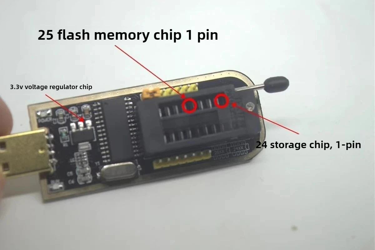


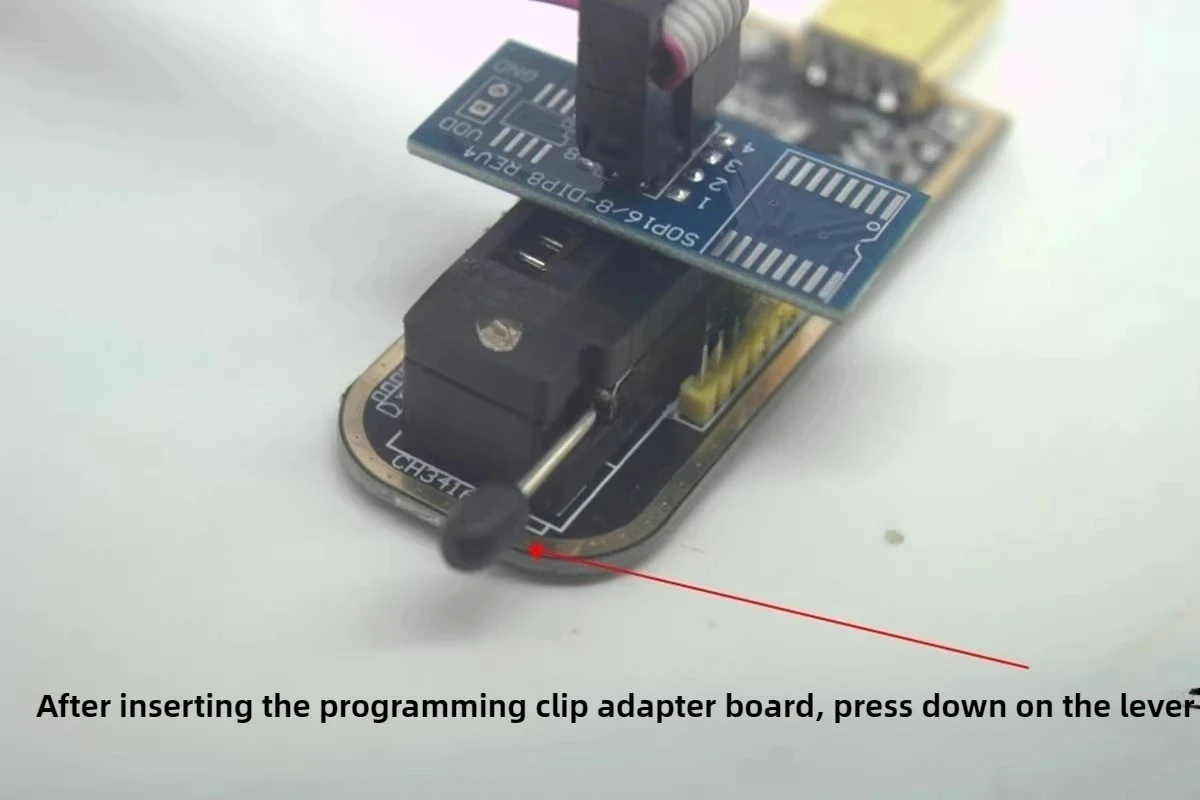


 Operation process of 341A programmer
Do not activate the software automatically, manual operation is required
Firstly, identify the chip model
2. Click Read again to save the program in the original chip that needs to be retained.
3 and then erase
4. Open a new file again
5 clicks to write (programming)
After writing the entry, the software will automatically validate it
Just close the software or unplug it directly






1PCS CH341A CH341B 24 25 Series EEPROM Flash BIOS USB Programmer Module SOIC8 SOP8 Test Clip For EEPROM 93CXX / 25CXX / 24CXX
$14.72
Sale price
$14.72
Regular price
$0.00
Description
SPECIFICATIONS
Brand Name: NONE
Certification: CE,RoHS
Does it include a Battery?: No
Does it include wireless functionality?: No
EU LVD Voltage: Low voltage: Below 50Vac or 75Vdc
High-concerned chemical: none
Origin: Mainland China
Voltage: 5 V 12 V 20 V 30 V
电压: 1V 2V 4V 5V 12V 12V 等 或自定义
USB Programmer
Condition: New
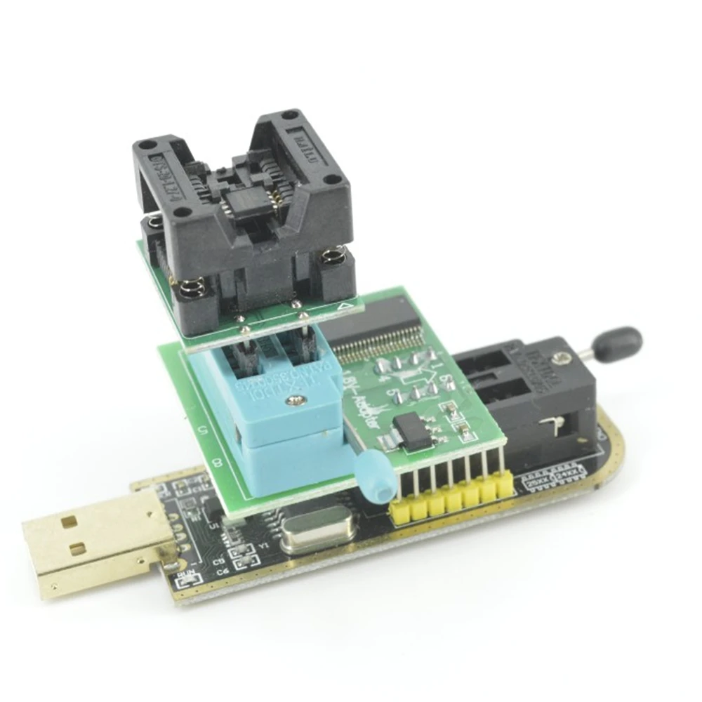
Support 24EEPROM and 25 SPI flash 8pin/16pin chip
USB to TTL port, can getroot online
With CH341A chip
Recognize 25 series chip automatically
And support download STC series procedure of singlechip
With 24/25 status indicator lamp
SPI pin to support expanding the utility
Color is shown as pictures
PLS NOTE that due to lighting effects, monitor's brightness/ contrass settings ect, there could be some slight differences in the color tone of the pictures and the actual item!
Provide 5V-3.3V power supply output
Dimension:70mm x 27mm
link: https://pan.baidu.com/s/1KCCoORA-g-wcGpSzg0p9PA
Extracted code:dcc2
Driver download webpage link:
https://www.jb51.net/softs/658262.html#downintro2(Drivers and software)
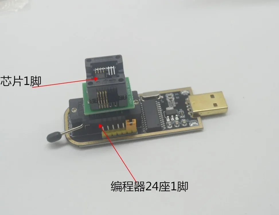
【 BIOS Chip Connection Method and Chip Pin Map 】: Because the BIOS chip of a tablet is not directly plugged in and out like a desktop computer, it is important to pay attention to the corresponding pin positions when connecting the BIOS chip with the SOP8 test clip. Reversing the connection and burning the chip will not be worth the loss. The BIOS chip of this machine has a pin with a small circular dot on pin 1. Generally, there is a colored wire on the test clip cable, which is the first wire. Let this wire correspond to pin 1 of the chip. This way, only check whether pin 1 on the test clip and the programmer correspond to each other to ensure accuracy. Attention should also be paid to whether the pins on the test clip and cable connection adapter board are plugged in correspondingly.
【 Programming software flashing BIOS 】: After confirming that the chip is connected correctly, connect to the computer. Open the programming software and check if the chip information has been read. 2-- Erase, the process is slow, taking several tens of seconds. 3- Check empty, confirm empty. 4- Open and select the bin file. 5- Programming, about a few minutes. 6- Verification is required.
After completing the above steps, you can solder on the power supply and turn it on to check. When there is no power, a few lines of English letters will appear, which is also successful. After charging for a while, it can be turned on normally and enter the system normally.
Operation process of 341A programmer Do not activate the software automatically, manual operation is required
Firstly, identify the chip model
2. Click Read again to save the program in the original chip that needs to be retained.
3 and then erase
4. Open a new file again
5 clicks to write (programming)
After writing the entry, the software will automatically validate it
Just close the software or unplug it directly
.............
Free Shipping Over $199
- Standard Shipping: Standard Shipping (12–18 Business Days)
- Express Shipping: Expedited Shipping (5–9 Business Days)
- Free Shipping: Orders over $199 qualify automatically
- Tracking: Full tracking number provided for all orders
30-Day Return Policy
- Returns: 30-day hassle-free return window
- Condition: Items must be unused and in original packaging
- Refund: Full refund processed within 3-5 business days
Why Choose Us?
- Factory Direct: ISO/TS 16949 certified manufacturer
- Quality: 100% electrical continuity tested before shipment
- Experience: 15+ years in automotive connector industry
- Support: Professional technical support available

You may also like
Blog posts
Title
An excerpt of your blog post's content
Title
Date|Author
Subscribe to our emails
Be the first to know about new collections and special offers.