

3-24V 8 Bit Blue/Red Common anode/cathode LED indicator Module Breadboard starter kit Board for MCU ARM 3d printer UNO MEGA2560
1pcs Red-Anode
$6.93
Sale price
$6.93
Regular price
$0.00
Skip to product information


3-24V 8 Bit Blue/Red Common anode/cathode LED indicator Module Breadboard starter kit Board for MCU ARM 3d printer UNO MEGA2560
$6.93
Sale price
$6.93
Regular price
$0.00
Description
SPECIFICATIONS
Application: Computer
Brand Name: LAUBEI
Choice: yes
Condition: New
Dissipation Power: w
High-concerned chemical: none
Origin: Mainland China
Package: SMD
Supply Voltage: 3-24v
Type: Voltage Regulator
is_customized: Yes
Product Name: 3.3V 5V 8-bit blue/Red common anode/cathode LED Indicator module diy kit for Arduiuo NANO UNO Raspberry PI 4 nodemcu
Packing list: 1 DC 3-24V 8-bit blue/red common anode/cathode LED lamp strip;
Description: Can be inserted directly into the breadboard, Perfect for connecting your Arduiuo UNO Mini Nano Mega2560 DUE bread board etc or other MCU (AVR STM32 ARM7 ARM9 ARM10 ARM11 PIC C8051 STC MSP430 FPGA/CPLD Etc.)
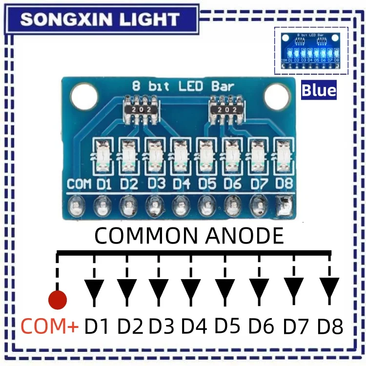
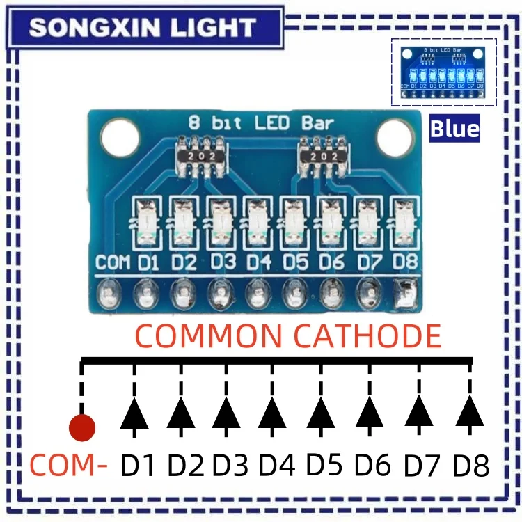
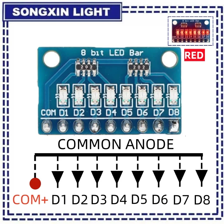
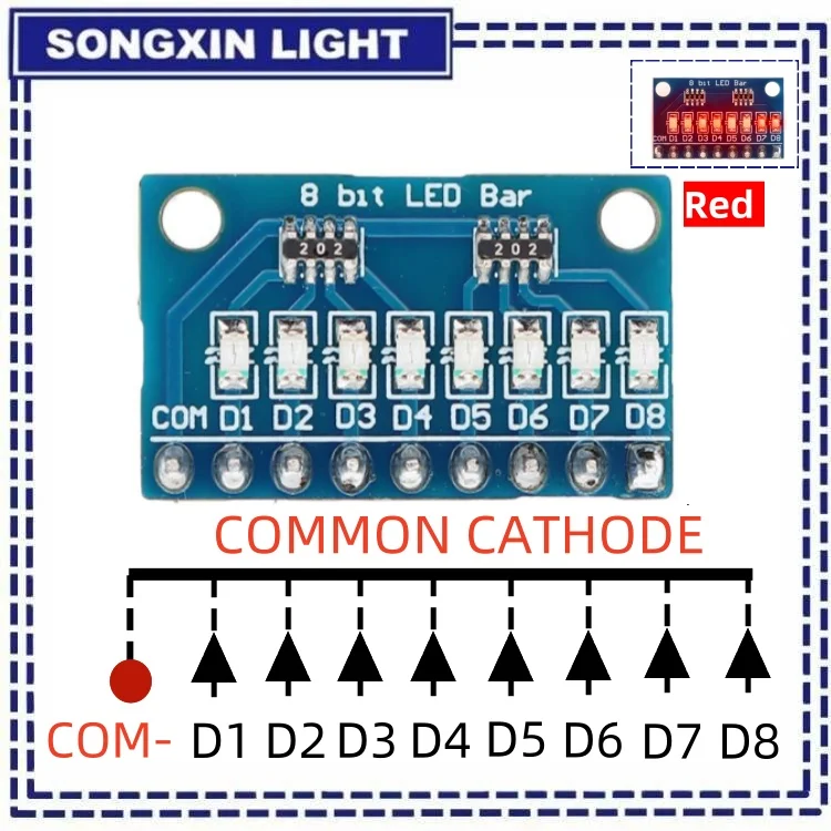
DC 3.3V 3.7V 5V 12V 24V 8-bit blue/red common anode/cathode LED bar
Product Name: 8-Bit LED Bar Graph Module
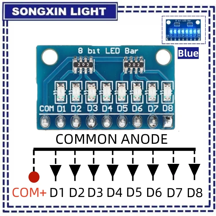
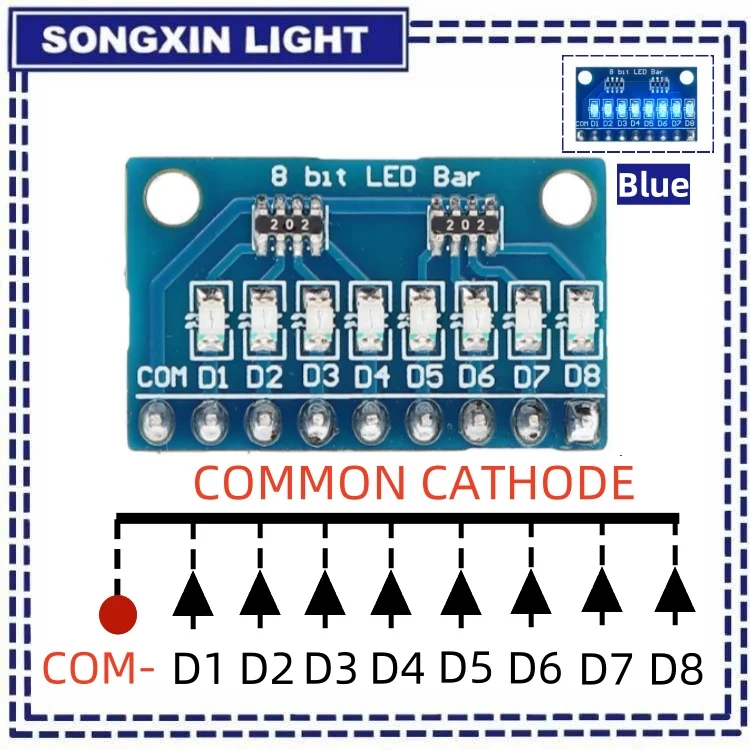
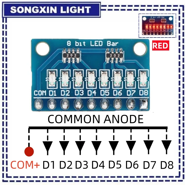
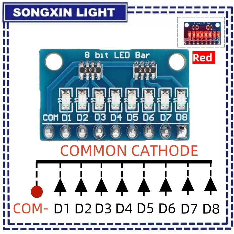
Description: This module consists of eight individual LED bars, each with its own common cathode and anode. The LEDs can be controlled individually to create a variety of visual effects.
-
Specifications:
Input voltage: 3.3V - 5V
Current consumption: up to 20mA per LED
Dimensions: 30mm x 20mm
Interface: solder pads for direct connection to a microcontroller or other circuitry
-
Applications:
Displaying numerical data such as sensor readings or battery levels
Creating simple animations or visual effects
Indicating the status of a system or device
-
Usage Notes:
Each LED bar has two pins: one for the common cathode and one for the anode. To turn on an LED, connect the cathode pin to ground and the anode pin to a positive voltage.
The current through each LED can be adjusted by adding a resistor in series with the anode pin.
The module can be powered directly from a microcontroller's digital output pins, but care should be taken not to exceed the maximum current rating of the pins.
Here is a brief description of how to wire the 8-bit LED bar graph module:
-
Connect the negative terminal of your power source to the common cathode pin of the module.
For each individual LED, connect the positive terminal of your power source through an appropriate resistor to the corresponding positive pin.
Remember to ensure that your power supply voltage does not exceed the maximum rated voltage for the LEDs, and use proper current-limiting resistors to prevent damage to the LEDs due to excessive current flow.
-
-
Free Shipping Over $199
- Standard Shipping: Standard Shipping (12–18 Business Days)
- Express Shipping: Expedited Shipping (5–9 Business Days)
- Free Shipping: Orders over $199 qualify automatically
- Tracking: Full tracking number provided for all orders
30-Day Return Policy
- Returns: 30-day hassle-free return window
- Condition: Items must be unused and in original packaging
- Refund: Full refund processed within 3-5 business days
Why Choose Us?
- Factory Direct: ISO/TS 16949 certified manufacturer
- Quality: 100% electrical continuity tested before shipment
- Experience: 15+ years in automotive connector industry
- Support: Professional technical support available

You may also like
Blog posts
Title
An excerpt of your blog post's content
Title
Date|Author
Subscribe to our emails
Be the first to know about new collections and special offers.