

4-Channel MOSFET Switch Module – IRF540N V4.0+ with Optocoupler Isolation for Arduino, High-Power Load Control (1/4 Way)
1 channel
$11.70
Sale price
$11.70
Regular price
$0.00
Skip to product information


4-Channel MOSFET Switch Module – IRF540N V4.0+ with Optocoupler Isolation for Arduino, High-Power Load Control (1/4 Way)
$11.70
Sale price
$11.70
Regular price
$0.00
Description
SPECIFICATIONS
Application: Computer
Brand Name: SZFYDOSH
Choice: yes
Condition: New
Dissipation Power: n/a
High-concerned chemical: none
Origin: Mainland China
Supply Voltage: 12v
Type: Module
is_customized: Yes
Product description
1.MOSFET is an electronic device with good switching characteristics, and is widely used in circuits that require electronic switching, such as switching power supplies and motor drives, and lighting dimming. Relay is another module with switching characteristics that everyone is very familiar with. However, because the working principle of relays generally relies on mechanical contacts to achieve the purpose of opening and closing, it will inevitably lead to a very short switching time. In the case of inability to work, the beeping sound when the contact switch is made is also an annoying thing in some occasions.
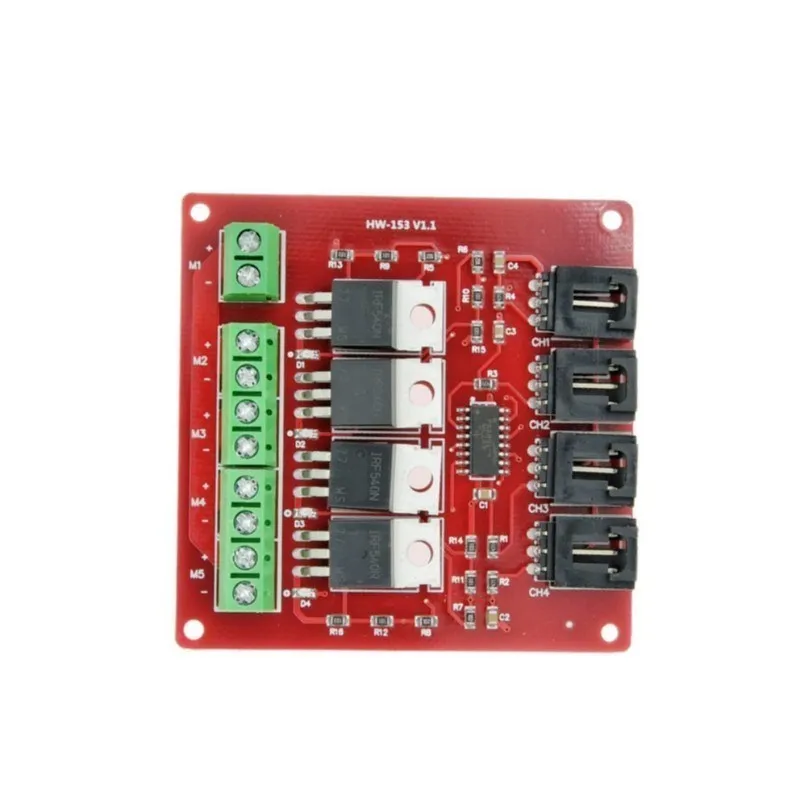
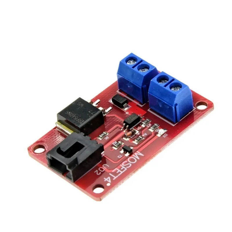
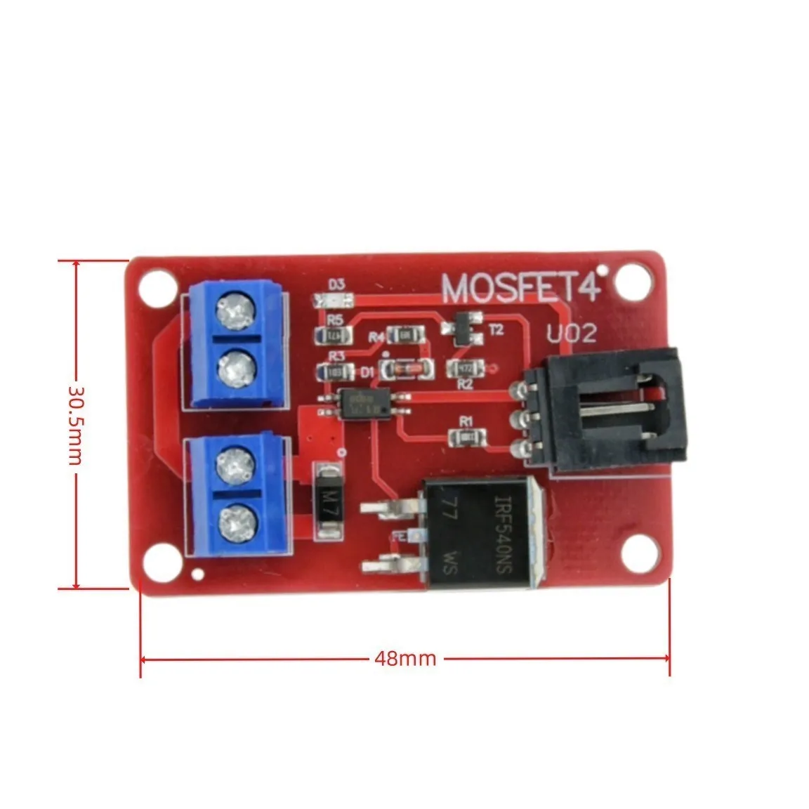
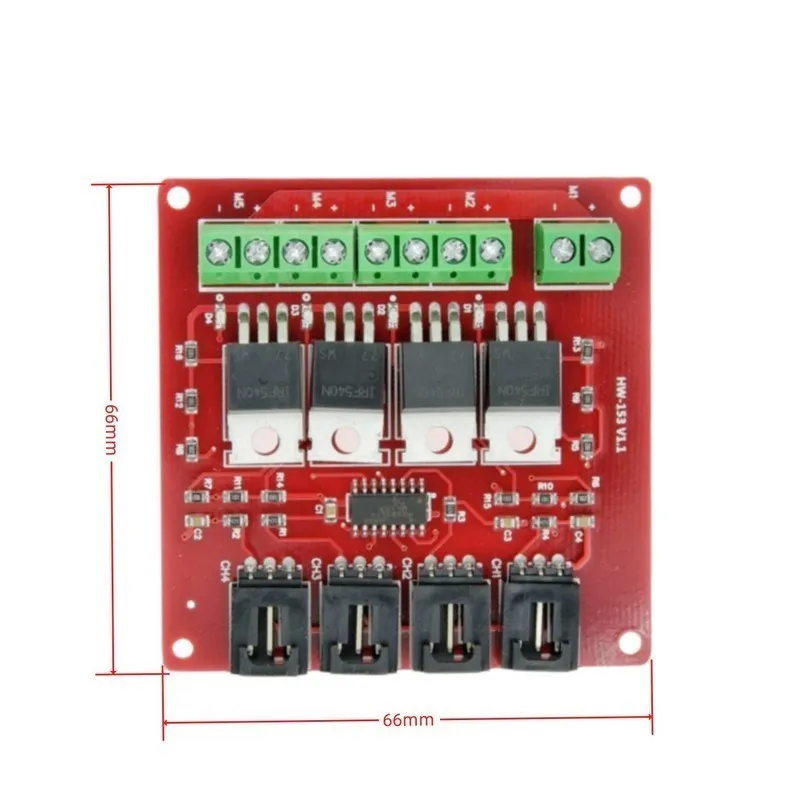
2.The 4-way MOSFET switch we designed can provide up to 4 groups of electronic switches, which are used to control different circuit modules. Affected by the working principle of MOSFET, this electronic building block can only be used to control DC circuits, such as DC LED screens, etc., and is not suitable for the control of AC circuits. The MOSFET switch can be used to control a 100V/33A DC circuit under extreme conditions, but the minimum DC voltage for control is recommended not to be lower than 9V.
3.In the circuit connection, the connection of the controlled end is a little more troublesome. Take the control of 12V LED strips as an example, first connect the power supply between the positive pole (+) and the negative pole (-);
4.Then connect the positive pole of the LED strip to the positive pole (+) of the module, and the negative pole of the LED strip to the switch 1 (S1);
5.If there are other LED strips that need to be controlled, just connect the positive pole of the LED strip to the positive pole (+) of the module, and connect the negative pole of the LED strip to switch 2 (S2), switch 3 (S3), switch 4 (S4) on;
6.The connection of the control terminal is much simpler. We only need to connect the corresponding control port with the Arduino sensor expansion board through the sensor connection line, and then we can control these 12V LED strips through the Arduino. In the experiment, we connected two LED strips.
Free Shipping Over $199
- Standard Shipping: Standard Shipping (12–18 Business Days)
- Express Shipping: Expedited Shipping (5–9 Business Days)
- Free Shipping: Orders over $199 qualify automatically
- Tracking: Full tracking number provided for all orders
30-Day Return Policy
- Returns: 30-day hassle-free return window
- Condition: Items must be unused and in original packaging
- Refund: Full refund processed within 3-5 business days
Why Choose Us?
- Factory Direct: ISO/TS 16949 certified manufacturer
- Quality: 100% electrical continuity tested before shipment
- Experience: 15+ years in automotive connector industry
- Support: Professional technical support available

You may also like
Blog posts
Title
An excerpt of your blog post's content
Title
Date|Author
Subscribe to our emails
Be the first to know about new collections and special offers.