

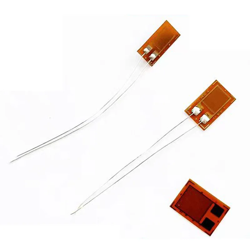
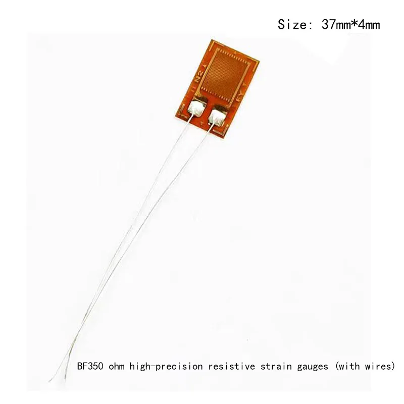
5PCS BF350/BX120 ohm High Precision Resistive Strain Gauge/Strain Gauge for Pressure/Weight Transducers
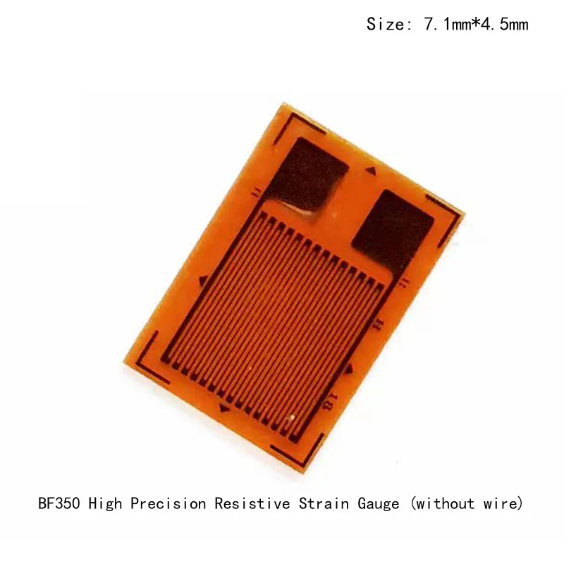
BF350(without cable)
$9.45
Sale price
$9.45
Regular price
$0.00
Skip to product information


5PCS BF350/BX120 ohm High Precision Resistive Strain Gauge/Strain Gauge for Pressure/Weight Transducers
$9.45
Sale price
$9.45
Regular price
$0.00
Description
SPECIFICATIONS
Application: standard
Brand Name: PENGHEKEJI
Choice: yes
Condition: New
Dissipation Power: standard
High-concerned chemical: none
Operating Temperature: standard
Origin: Mainland China
Supply Voltage: standard
Type: Module
is_customized: Yes
semi_Choice: yes
Fatigue life 1 million times
Model:BF350-3AA Type Copper metal foil resistance strain gauge
Resistance 349.8+/-0.1 Ohm
Sensitivity factor: 2.0-2.20
Accuracy grade: 0.02 grade
Strain limit:2.0 hundred
Single chip size:7.5mm*4.9mm
Typical resistance value: 350Ω
Grid Material:Constantan
Gauge Factor: 2.00-2.20
Sensitivity Factor Dispersion:≤±1 hundred
Strain Limit: 2.0 hundred
Fatigue life: ≥1M
Matrix Dimension (L×W): 7.1mm*4.5mm
Modified phenolic base, made of copper foil, static measurement stability, fatigue life, creep, strain limit and other characteristics of good, this specification is easy to paste and welding, good heat dissipation, power consumption per unit area is small.
Commonly used in general metal materials and other similar elastomers.
I. Classification of strain gauges
According to the sensitive grid material can be divided into metal, semiconductor and metal or metal oxide paste and other three categories:
1, metal strain gages Including silk (silk winding type, short connection type) strain gages, foil type strain gages and thin film strain gages;
2, semiconductor strain gages including body type semiconductor strain gages, diffusion type semiconductor strain gages and thin film semiconductor strain gages;
3、Metal or metal oxide pastes are mainly used to make thick film strain gauges.
All of our store is foil type metal strain gauge.
Second, the main parameters of the strain gauge
1、Strain gauge resistance
The resistance of strain gauge refers to the resistance value of strain gauge measured in room temperature environment, without installation and without force.
Selection of the resistance value of the strain gage is mainly based on the measurement object and the requirements of the measuring instrument.
2, the sensitivity factor of the strain gauge
The sensitivity factor of strain gage means: when the strain gage is pasted on the surface of the specimen in a unidirectional stress state, and its longitudinal direction (sensitive grid longitudinal direction) and parallel to the stress direction, the rate of change of the strain gage resistance and the specimen surface patch along the stress direction of the strain (i.e., along the longitudinal strain strain gage) of the ratio of the equation, i.e., K is the sensitivity factor of the strain gage; ε is the specimen surface measurement point at the longitudinal direction of the strain gage sensitive grid parallel strain; RRΔ is the relative change of the strain gage resistance caused by ε. The strain of strain gage resistance caused by ε is the relative change of the strain gage resistance. ε is the strain parallel to the longitudinal line of the strain gage sensitive grid at the measuring point on the surface of the specimen; RRΔ is the relative change in the resistance of the strain gage caused by ε.
The sensitivity coefficient of the strain gauge depends mainly on the sensitivity coefficient of the sensitive grating material, but the two are not equal, which is mainly due to two reasons: the silk type strain gauge, for example, due to the presence of the transverse grating, so that the sensitive grating made of sensitive grating after the sensitive coefficient is smaller than that of the silk material, the size of the difference is related to the sensitive grating structural type and geometric dimensions; the deformation of the surface of the specimen is through the base and the bonding agent is transferred to the sensitive grating, due to end The deformation of the specimen surface is transferred to the sensitive grating through the substrate and binder, and the influence of the transition zone makes the sensitivity coefficient of the strain gauge smaller than that of the sensitive grating, and the difference is not only related to the type of the substrate and binder and its thickness, but also affected by the degree of curing of the binder and the quality of the installation of the strain gauge. Therefore, the sensitivity coefficient of the strain gauge is a comprehensive index affected by a variety of factors, it can not be obtained through theoretical calculations, but by the manufacturer by sampling in the special equipment to determine the calibration test. And its average nominal value and standard error indicated on the package. Commonly used strain gauge sensitivity factor of 2.0 ~ 2.4.
3、Strain limit of strain gauge
The strain limit of the strain gauge is defined as the constant temperature conditions, the installation of the strain gauge specimen gradually loaded, the indication of the strain and the measured member of the real strain of the relative error (usually specified as 10 hundred) does not exceed a certain value of the real strain value. In fact, the strain limit is expressed as the value of the strain gauge when the specified nonlinear error is not exceeded? Thbao Metallurgical Strain Gauge for Simply Simply Simple Pipe
The sensitivity coefficients of most sensitive grid materials vary very little over the elastic range, so in general, the main factor determining the magnitude of the strain limit is:
a. The performance of the binder and substrate materials in transferring the strain;
b. the form of arrangement of the lead wire to the solder joints of the sensitive grids;
c. the quality of the strain gage installation.
Selection of binder and substrate materials with high shear strength, controlling the substrate and binder layer not to be too thick when manufacturing and installing strain gages, proper curing treatment, etc.; all contribute to obtaining higher strain limits.
Increase in operating temperature, will make the strain limit decreased significantly, medium and high temperature strain gages in the limit of the working temperature of the strain limit are lower than the room temperature strain gages.
4、Fatigue life of strain gauge
The fatigue life of strain gauge means: under the action of constant amplitude alternating stress, the strain gauge works continuously until the number of cycles of fatigue damage.
When the strain gage one of the following three situations, can be considered fatigue damage: a. Sensitive grid or lead breaks; b. Strain gage output amplitude change 10 hundred; c. Strain gage output waveform spike spike.
The reason for fatigue damage is that, in dynamic stress measurement, strain gages under the action of alternating strain, after a number of cycles, its sensitivity factor will change with the increase in the number of strain cycles. This is mainly due to defects in the sensitive grids (pinholes and cracks in the grids), changes in the contact resistance of the internal weld joints, a decrease in the strength of the bonding agent, and poor quality of the strain gauge installation. To improve the fatigue life of strain gages, special attention must be paid to the connection between the leads and the sensitive grids and the quality of the solder joints.
Third, the structure of the strain gauge
Resistance strain gage is mainly composed of sensitive grid, substrate, lead wire, cover layer, sensitive grid with adhesive bonded between the substrate and cover layer.
1, sensitive grid - with alloy wire or alloy foil made of the grid. It can be measured component surface strain is converted to resistance relative change. At present, the commonly used metal sensitive grid materials include copper-nickel alloy, nickel-chromium alloy, nickel-molybdenum alloy, iron-based alloys, platinum-based alloys, palladium-based alloys and so on.
2, substrate - a component of the resistance strain gauge. Its role is in the strain gage is installed on the specimen before the sensitive grids permanently or temporarily placed on it, but also to make the sensitive grids and paste the strain gage between the specimen mutual insulation. Commonly used substrate materials are paper, film (epoxy resin, phenolic resin, polyester resin and polyimide, etc.), fiberglass cloth, metal flakes.
3, the lead - resistance strain gauge leads from the sensitive grid lead wire or strip metal wire. Usually the lead is in the manufacture of strain gages and sensitive grids connected to become part of the strain gage.
4, cover layer - resistance strain gauge cover layer is used to protect the sensitive grid to avoid mechanical damage or prevent oxidation at high temperatures. Commonly used to make the substrate film or soaked in organic glue (such as epoxy resin, phenolic resin, etc.) of glass fiber cloth as a cover layer, but also in the sensitive grid coated with the binder used in the preparation as a protective layer. The materials of the cover layer include paper, adhesive film and fiberglass cloth.
Fourth, metal resistance strain gauge application and working principle
Resistance strain gauge has two applications: one is as a sensitive element, directly used for the strain measurement of the test piece; the other is as a conversion element, through the elastic element constitutes a sensor, used for any can be converted into an elastic element strain of other physical quantities for indirect measurement. When measuring with strain gauges, they are pasted on the surface of the object to be measured. When the measured object is deformed by force, the sensitive grid of the strain gage is also deformed, and its resistance value changes accordingly, which is converted into voltage or current by the conversion circuit to realize the measurement of strain.
The working principle of metal resistance strain gauge is resistance strain effect, that is, when the metal wire is subjected to stress, its resistance changes along with the mechanical deformation (tensile?). The resistance of the wire changes according to the mechanical deformation (stretching?). The size of the corresponding changes. The theoretical formula for the resistance-strain effect is as follows.
R=ρ*(L/S)
Where: ρ - resistivity (Ω - mm2 / m) L - the length of the wire (m) S - the cross-sectional area of the wire (mm2)
From the above formula, it can be seen that the metal wire is subjected to stress and mechanical deformation process, ρ, L, S, all three to change, which will inevitably cause changes in the resistance value of the wire. When stretched by the external force, the length increases, the cross-sectional area decreases, the resistance value increases; when shortened by the pressure, the length decreases, the cross-sectional area increases, the resistance value decreases. Therefore, as long as you can measure the change in resistance value, you can know the strain of the wire. This conversion relationship is
ΔR/R=Koε
Where: R - the amount of change in the resistance value of the wire.
Ko - the strain sensitivity factor of the metal material, which is mainly determined by the test method, and in the elastic limit is basically a constant value; ε
ε - the axial strain value of the metal material, that is, ε = ΔL / L, so also known as ε for the length of the strain value of the wire, the value of its diligence in the 0.24 ~ 0.4 between.
In practical application, the metal resistance strain gauges are pasted on the elastic element of the sensor or on the surface of the measured mechanical parts. When the sensor in the elastic element or the measured mechanical parts by the force generated strain, pasted on the strain gauges on the same mechanical deformation occurs, resulting in corresponding changes in the resistance of the strain gauges. At this point, the resistance strain gauge will be converted into mechanical changes in the resistance of the output.
Specification of BF series sold
Substrate: Modified phenolic; Grid wire: Con copper (copper alloy containing 40% nickel, 1.5% manganese); Totally enclosed structure; Temperature self-compensation and creep self-compensation can be realized at the same time.
High precision, good stability, easy to use, suitable for 0.02 level sensors.
Main technical indicators: BF series
Typical resistance value: 350 ohm
Tolerance of average resistance value:≤±0.1 hundred
Sensitivity factor: 2.12
Sensitivity coefficient dispersion:≤±1 hundred
Strain limit:2.0 hundred
Fatigue life:≥1M
Temperature self-compensation coefficient:9,11,16,23,27
Operating temperature range:-30-+150
Grid Material Constantan
Substrate Epoxy-modified phenolic
Substrate Thickness (um) 32±1
Insulation Resistance 10000 ohm
BF350-3AA (23) N8
Model No. L x W 3.1 x 3.5
Substrate size LxW 7.5x4.9
Strain gauge model number N * for the creep labeling, labeling is different, the creep value is different, the law is:
(+) N9>N7>N5>N3>N1>N0>N8>N6>N4>N2>T0>T2>T4>T6>T8>T1>T3>T5 (-) the actual creep value of the difference between neighboring labels 0.01-0.015 hundred FS/30min
Circuit principle (see figure):
Usually the sensor uses four pieces of equal value resistors Huicholton equal bridge circuit. r, B for the input, G, W for the output, RS play a role in protecting the circuit. The zero balance of the circuit is adjusted by adjusting RS and R1.
High Precision Resistive Strain Gauges / Strain Gages / GAGE / Full Bridge (for Pressure / Load Cells)
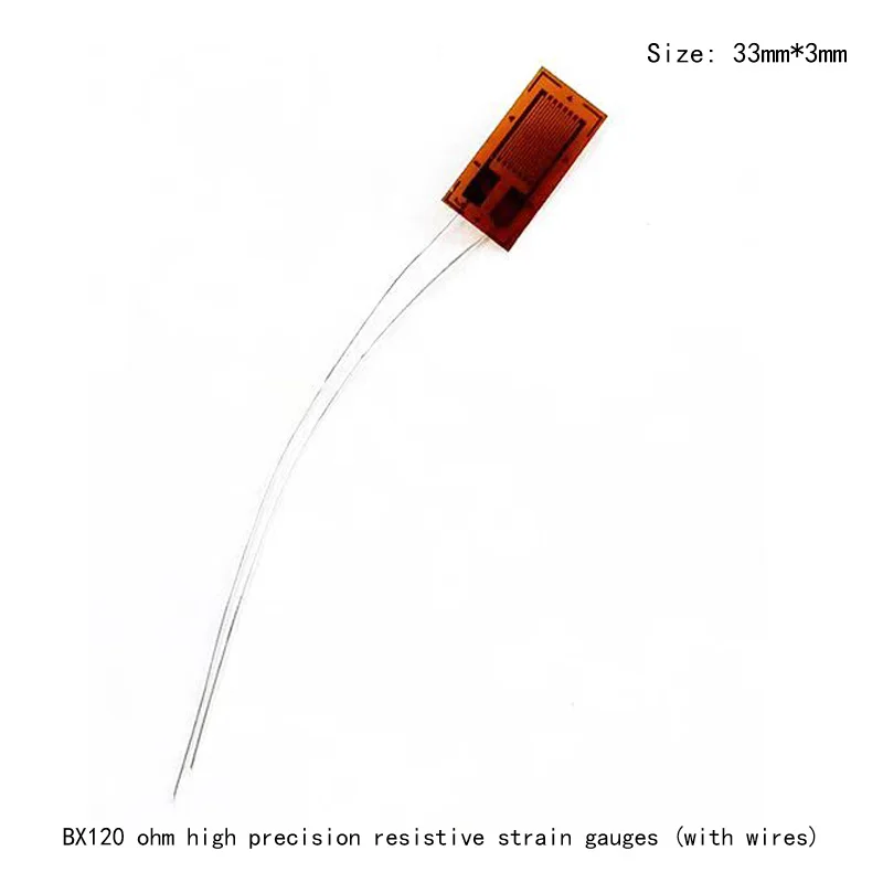
BX120-3AA Resistance Strain Gauge
Resistance resistance value 120 ohm
Foil type resistance strain gauge/temperature self-compensated/normal temperature strain gauge BE/BX120 ohm -3aa
Grade: Grade A
Strain limit:2%
Use temperature: -30~+80 degrees


Free Shipping Over $199
- Standard Shipping: Standard Shipping (12–18 Business Days)
- Express Shipping: Expedited Shipping (5–9 Business Days)
- Free Shipping: Orders over $199 qualify automatically
- Tracking: Full tracking number provided for all orders
30-Day Return Policy
- Returns: 30-day hassle-free return window
- Condition: Items must be unused and in original packaging
- Refund: Full refund processed within 3-5 business days
Why Choose Us?
- Factory Direct: ISO/TS 16949 certified manufacturer
- Quality: 100% electrical continuity tested before shipment
- Experience: 15+ years in automotive connector industry
- Support: Professional technical support available

You may also like
Blog posts
Title
An excerpt of your blog post's content
Title
Date|Author
Subscribe to our emails
Be the first to know about new collections and special offers.