

6 Inputs and 8 Outputs Decoding Board Audio and Video Development Board ADAU1452 DSP CS42448 Audio Module 48-192 Sampling Rate W
1452 CS42448 USBi / China Mainland
$553.55
Sale price
$553.55
Regular price
$0.00
Skip to product information


6 Inputs and 8 Outputs Decoding Board Audio and Video Development Board ADAU1452 DSP CS42448 Audio Module 48-192 Sampling Rate W
$553.55
Sale price
$553.55
Regular price
$0.00
Description
SPECIFICATIONS
Brand Name: NoEnName_Null
Bundle: Bundle 1
Certification: NONE
Compatible Audio & Video Equipment Style: Digital-to-Analog Converter (DAC),Professional Audio Equipment,Stage Equipment
Dimensions (WxHxD)): 72mm*73mm*28mm
High-concerned chemical: Tris(2-chloroethyl) phosphate
Model Number: ADAU1452
Origin: Mainland China
Package: Yes
Weight: 30G
size:72mm*73mm*28 mm ±2 mm
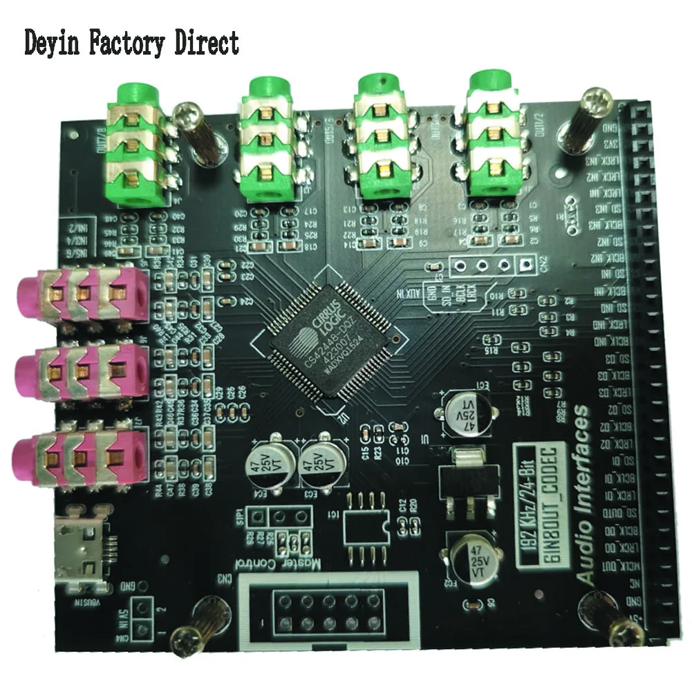
CS42448 -CODEC 6-in-8-out decoding board
AD1938-CODEC 4-in-8-out decoding board
Audio module development tool.
Factory direct sales, high cost-effective hot selling products. Welcome to place orders for quality assurance.
It is recommended to purchase our emulation burner at the same time for development (USBI with 288 shell), and the package purchase will be more favorable. Materials include schematics and routines sent via email.
Due to the recent chip shortage, MCU_STM32F103C8T6 does not have a patch on the actual shipping board. The MCU itself has no program and can still work normally without a board. The AD1938_CODEC decoding board adds a microcontroller for soft control, which can set the sampling rate and audio interface type.
The on-board routine provides input and output IIS/SPDIF (off fiber/coaxial selection) interface (single ADAU1450-DSP board does not support SPDIF);
1. For the ADAU1452 series routines, the configuration page can freely select the communication method (SPI or I2C) between SIGMASTUDIO and the target board. The SPI mode address is: SPI 0x1 ADR0, the I2C address is: I2C 0x16 (118), and E2Prom is SPI 0x1 ADR0, no need to change.
2. Definition of the link method between USBi and the target board (ADAU1452dsp board):
SPI communication method: USBi end 1/3/5/7/9 (CLK/CS/MISO/MOSI/GND) of the emulator respectively correspond to 5/4/3/2/1 of the target board (ADAU1452dsp board) CN2. Just follow Arrange in order.
I2C communication method: USBi terminal 2/4/6 (GND/SCL/SDA) of the emulator correspond to 1/5/3 of CN2 of the target board (ADAU1452dsp board) respectively.
3. SIP1 on the target board is used as an auto-start jumper, which is actually basically useless. There is no need to cancel auto-start, so you can throw away the jumper cap and try not to plug it into terminal 12.
4. The factory test routine is: ADAU1452 electrical splitting routine 192tdm.dspproj file, the matching AD1938 defaults to 192K/TDM audio transmission, 4 channels in and 8 channels out. If you need to change the sampling rate and audio interface mode, you can refer to the AD1938 board Note about jumpers, otherwise the sound will not be normal.
5. Beginners are recommended to use the CODEC decoding of CS42448, which supports 6 channels into 8 channels for output. It has a separate routine. The factory routine is the file 1452_cs42448_192.dspproj. In addition to higher indicators, the circuit is simple and stable, 48 -192 sampling rate takes all, no need to switch configurations, just concentrate on debugging DSP.
The factory setting is 192K_TDM format, OUT3/OUT4 are straight-through interfaces, and OUT1/OUT2 are stereo 2-way mode output interfaces.
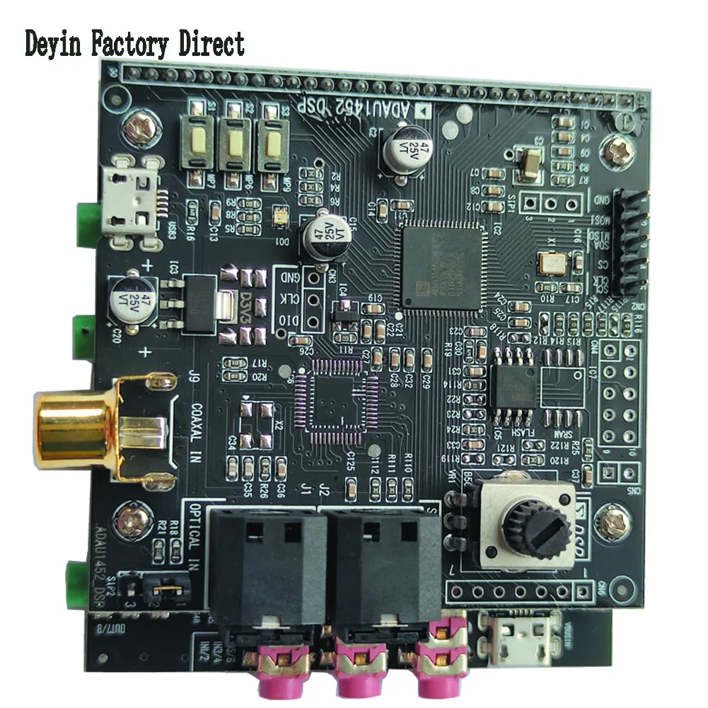
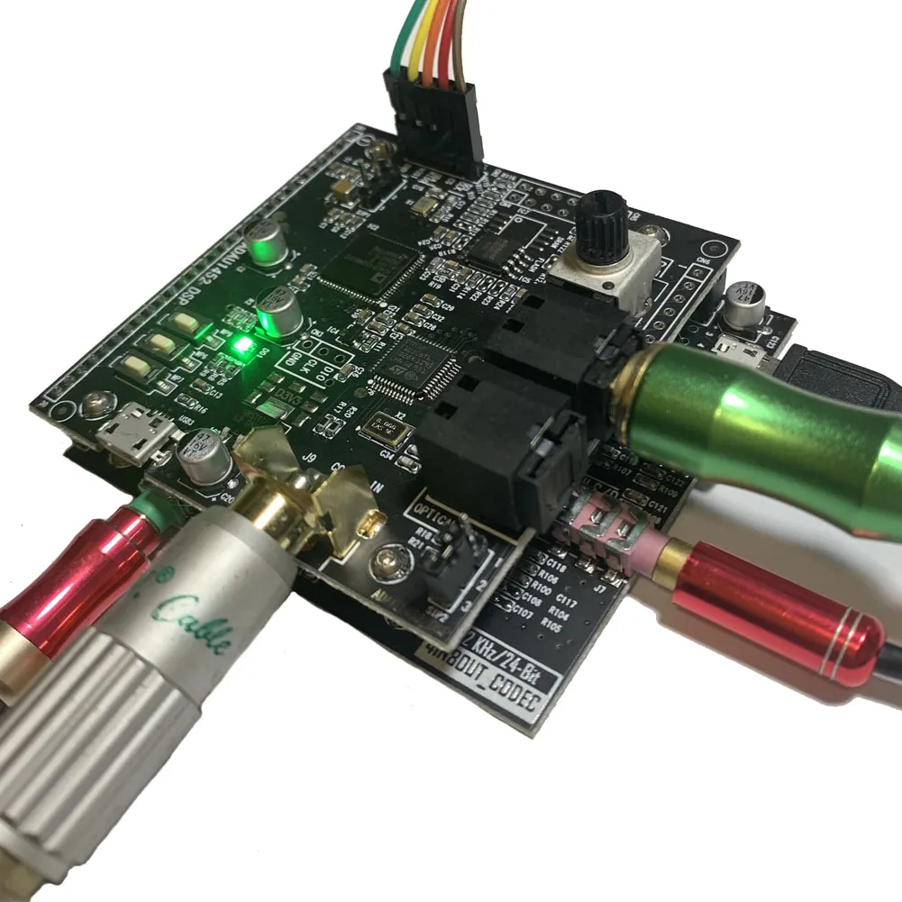
S1 button input selection; the blue light flashes for SPDIF input, the red light indicates IN2 analog input. The green light indicates IN1 analog input.
S2 button preset EQ switching, a total of 10 EQ presets.
The S3 button super bass switch is useful in the electronic crossover subwoofer channel and is turned on by default;
The three-color LED flashes to display the input channel and working status respectively;
The STM32 microcontroller is reserved on the board. You can choose to use the microcontroller to control the DSP, leaving USB/uart/spi ports. It can also be used as a microcontroller development board.
Potentiometer ADC acquisition for volume control, LED driver example.
6 inputs and 8 outputs decoding board audio and video development board ADAU1452 DSP CS42448 audio module 48-192 sampling rate
Please purchase a single USBI simulation burner from other links in our store.
Technical support is unavailable, but development materials (including schematics and routines) will be provided. The product has undergone multiple tests before shipment. The customer service is not familiar with the technology. After receiving the product, power it on first to confirm that the board is running the program. If the LED lights are flashing, it indicates normal operation. The product is a qualified one. Thank you for your support!


 1452 DSP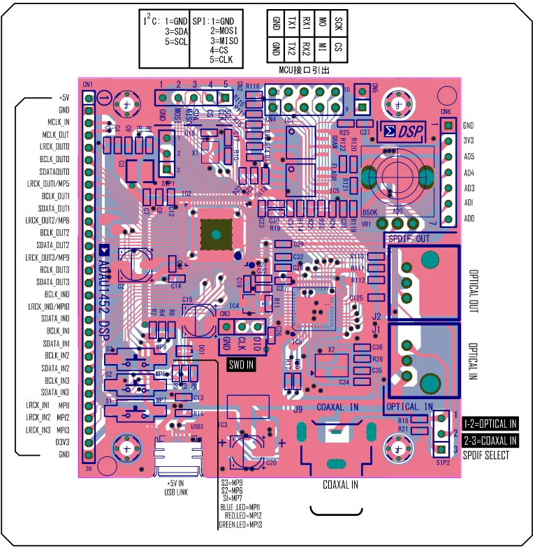
AD1938 schematic diagram 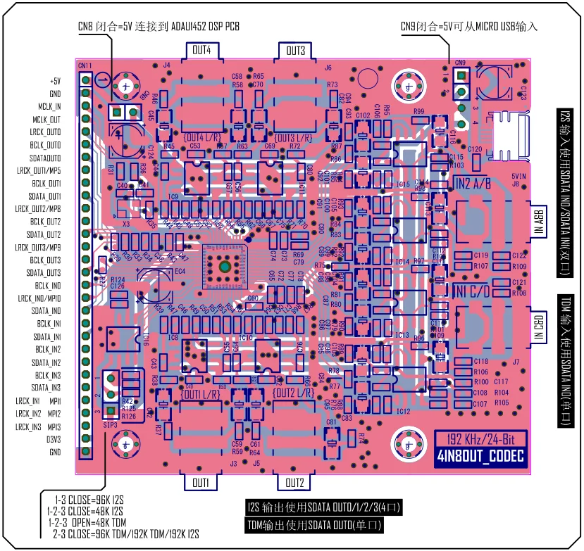
CS42448 schematic diagram
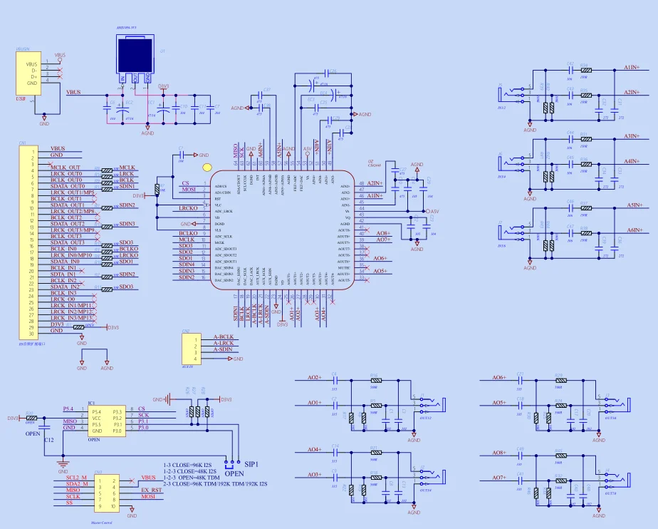

CS42448 Chip Introduction
108 dB 192 kHz 6-input, 8-output multi-channel codec
The CS42448 is a highly integrated audio codec designed to simplify the design of home theater and car audio systems. Audio products provide advanced multi-channel surround sound performance. The CS42448 supports the addition of up to eight single-ended or six differential audio input sources, and up to eight single-ended or differential output sources. Highly integrated, multiple audio channels can be passed to the DSP chip for audio processing without the need for external analog-to-digital (A/D) converters. The auxiliary serial input is available for two additional PCM (Pulse Code Modulation) data channels. The inputs are more powerful, enabling audio/video (A/V) receivers that can receive audio from multiple sources. The CS42448 eliminates clicks and pops caused by power switching. This IC is ideal for audio applications requiring wide dynamic range, negligible distortion and low noise.
ADAU1452 Chip Introduction
Analog Devices' ADAU1452 is an automotive-grade SigmaDSP audio processor with fully programmable enhanced sound processing. The 1.2V 32-bit SigmaDSP processing core operates at a frequency of 294.912MHz and a sampling rate of 48kHz per time, exceeding 6144 SIMD instructions. Mainly used in automotive audio processing, navigation systems, rear entertainment systems, DSP amplifiers, commercial and professional audio processing.
AD1938 Chip Introduction
The AD1938 is a high-performance, single-chip codec with four built-in input analog-to-digital converters (ADCs) and eight single-ended output digital-to-analog converters (DACs), using Analog Devices' multi-bit sigma-delta (Σ- Δ) Patent architecture. It has an SPI port through which the microcontroller can adjust the volume and many other parameters.
Development materials available (including schematics and routines)
Must-read Usage Instructions:
For the ADAU1452 series routines, the configuration page can freely choose the communication mode between SIGMASTUDIO and the target board (SPI or I2C). The address for SPI mode is: SPI 0x1 ADR0, and the address for I2C is: Both I2C 0x16 (118) and E2Prom are SPI 0x1 ADR0 and do not need to be modified.
2. Definition of the connection method between USBi and the target board (ADAU1452dsp board) :
SPI communication mode: The USBi terminal of the simulator 1/3/5/7/9(CLK/CS/MISO/MOSI/GND) correspond respectively to 5/4/3/2/1 of the target board (ADAU1452dsp board) CN2. They are arranged exactly in order.
I2C communication mode: 2/4/6 (GND/SCL/SDA) at the USBi terminal of the simulator correspond respectively to 1/5/3 of CN2 on the target board (ADAU1452dsp board).
3. The SIP1 on the target board serves as an auto-start jumper. In fact, it is basically useless and there is no need to cancel the auto-start at all. Therefore, you can throw away the jumper cap and try not to plug it into terminal 12.
4. The factory test routine is: The ADAU1452_tdm factory test (1938+42448).dSPproj file can be used for both AD1938 and CS42448 models. After delivery, it can be powered on to test the sound. It is processed by default at 96K_TDM, and all input and output channels are open by default. Just connect the audio source and headphones for testing. The blue LED flashing on the board indicates that it is working properly. If no audio source is connected, you can also turn on the potentiometer clockwise, and the internal signal generator will also produce sound.
5.ADAU1452 and ADAU1466 can be completely replaced, with only some differences in resources. For the provided routines, since the program occupation itself is not large, they can be fully compatible. There is no need to distinguish them. Just when importing your own product at the end, you need to select the corresponding chip and re-copy it in.
Free Shipping Over $199
- Standard Shipping: Standard Shipping (12–18 Business Days)
- Express Shipping: Expedited Shipping (5–9 Business Days)
- Free Shipping: Orders over $199 qualify automatically
- Tracking: Full tracking number provided for all orders
30-Day Return Policy
- Returns: 30-day hassle-free return window
- Condition: Items must be unused and in original packaging
- Refund: Full refund processed within 3-5 business days
Why Choose Us?
- Factory Direct: ISO/TS 16949 certified manufacturer
- Quality: 100% electrical continuity tested before shipment
- Experience: 15+ years in automotive connector industry
- Support: Professional technical support available

You may also like
Blog posts
Title
An excerpt of your blog post's content
Title
Date|Author
Subscribe to our emails
Be the first to know about new collections and special offers.