

Customized Sine Wave High Power IGBT Module Control 2000A Driver Board
driver board
$437.36
Sale price
$437.36
Regular price
$0.00
Skip to product information




Customized Sine Wave High Power IGBT Module Control 2000A Driver Board
$437.36
Sale price
$437.36
Regular price
$0.00
Description
SPECIFICATIONS
Brand Name: NONE
High-concerned chemical: none
Origin: Mainland China
Type: Furniture Leg
Cautionary reminder: This product is a high-voltage device, and it will be burnt immediately after the wrong connection. Friends who have no electronic foundation, do not buy this product. The technical support of this product is every week, and there is no time for technical support. Because this kind of product requires Certain electronic basis, this product does not support returns when sold, please be familiar with the buyer, so as not to cause unnecessary trouble, please be careful! Thank you for your cooperation.
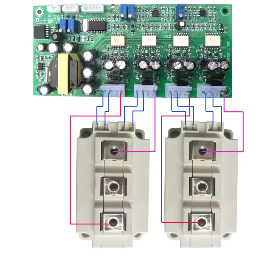
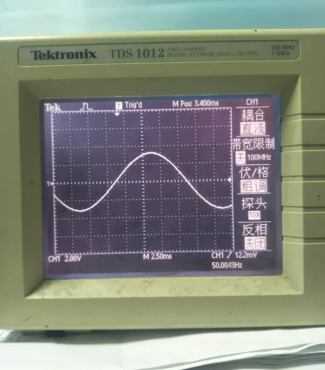
The sine wave high-power IGBT module control driver board is actually the rear-stage DC-to-AC part of the inverter, which converts the front-stage high-voltage direct current into an AC 220V output device.
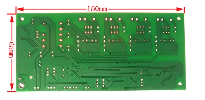
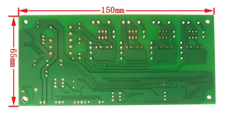
Now in the market, there are too many high-power IGBTs that are disassembled. The power is high and the price is cheap. I want to use these good resources to make a high-power sine wave inverter. If I want to make good use of these high-power IGBTs as an inverter , The sine wave control board should pay attention to two points, the dead time during work and the switching frequency during work, these two points are very important and fatal. The dead time of the control board is 2us, and the dead time of this board is 2.0us, which can be adapted to different sizes of IGBT modules, the carrier frequency SPWM is 16.000KHz, the control board has 50Hz/60Hz switching, with switch control, etc. Board size :15*6.5cm, this control driver board uses HCPL-316 drive protection circuit: integrated VCE saturation voltage drop detection, undervoltage lockout, soft shutdown and isolated fault feedback; always detects the saturation voltage drop of the chip 14 feet, when the voltage Over 7V, the output voltage of VOUT11 pin becomes low, FAULT (6 pin fault output) is low, and it is in the protection state.
New features: V3.0
1. Pure full high frequency inverter conversion circuit
2. Realize single-phase high-power inverter output
3. The output current. The power is constant and adjustable, which can realize the soft start of the motor
4. In constant current output mode, the output is always sine wave waveform
5. In the constant current output mode, the output is lower than 150V, and the output is turned off in 7 seconds
6. Under the condition of not using the display screen, the undervoltage protection point can be set from 0-220V
7. Support voltage, current, power display and adjustment
The IGBT module drive control board: the default startup time is 7 seconds, the dead zone is 2uS, and there is no output 150V undervoltage protection, which is convenient for beginners to install and use
Another program: start time 7 seconds, dead zone 2uS, output short circuit and 150V undervoltage protection, start adjustable constant current output, suitable for mass production and electronic master use.
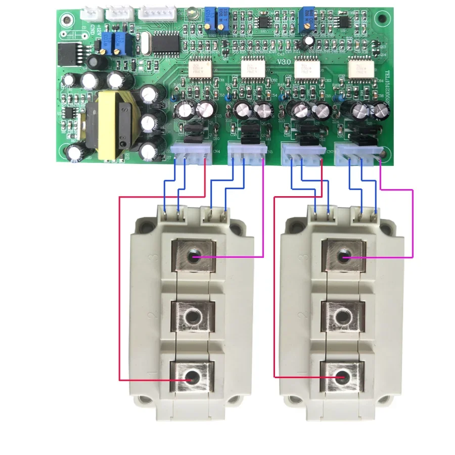
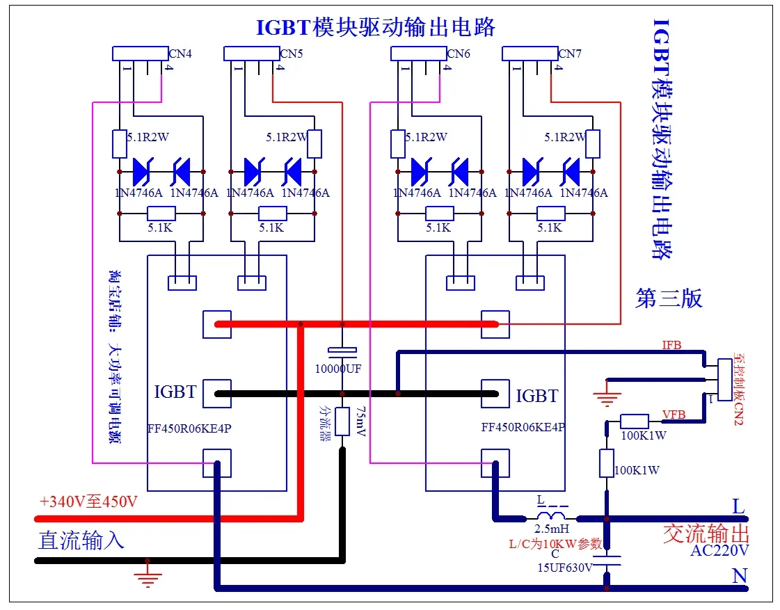
Matching output circuit diagram
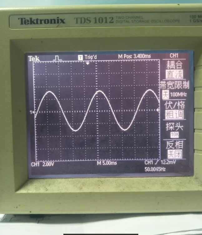
The voltage stabilization method of this control board adopts sine peak voltage stabilization, voltage instantaneous value feedback and effective value feedback structure, and double closed-loop control method. The effective value feedback of the outer loop voltage ensures that the output is as stable as possible when the system is in a steady state. The inner loop uses instantaneous value feedback to ensure that the system obtains excellent dynamic performance. The two perform their duties and cooperate together. Why I choose sine peak voltage regulation is because the transient closed-loop response is fast, the transient response is fast to the change of bus voltage and the change of output load, the control loop circuit is simple, and the control loop is easy to control. In addition, the instantaneous peak voltage is controlled by the inherent peak wave one by one. I have added a constant and adjustable output current to the start of electrical appliances, which is suitable for motor and anti-impact start.
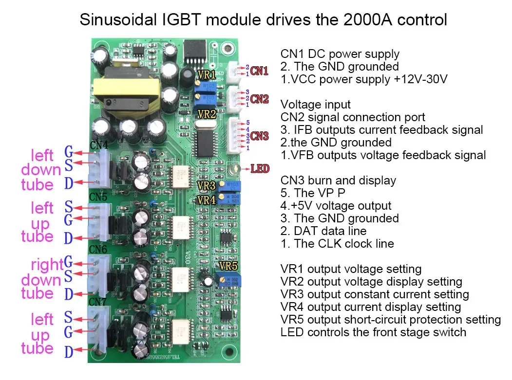
Part of the function description:
1. 50/60Hz switching: the default is 50Hz when power is on, and the 5.1K resistor welded to R17 is 60Hz;
2. Turn on/off conversion: the default is to turn on when the power is on, and the 10 pin of U1 is grounded for shutdown. This function is used for UPS mains/inverter switching, and the startup is in quick-start mode;
3. VR1 output voltage setting
4. VR2 output voltage display adjustment
5. VR3 output current setting
6. VR4 output current display adjustment
7. VR5 output over-power setting: it is the maximum value for adjusting the output power. At the maximum value, the top and bottom of the sine wave will be compressed into a straight line, indicating that the output power is already being limited;
CN1: DC power input
1. VCC power supply, +10V to +30V single power supply;
2. GND power supply negative electrode
CN2: Control
1. VFB is the output voltage feedback signal, which stabilizes the output voltage
2. GND power supply negative
3. IFB outputs current feedback signal to control the total current
CN3: Programming and display
Used for program burning, in addition, it can be directly connected to the LCD128*64 display screen to display the parameters directly
1. CLK clock line
2.DAT data cable
3. GND power supply negative
4. +5V output, to provide +5V power to the display and programmer
5. Use for vpp programming
CN8: Protection output
1. SD protection output, control the pre-stage boost switch, normal work 0V, protection 5V output, default access to LED lamp beads
2. GND power supply negative
Important note: The negative pole of the control board and the negative pole of the high-voltage bus must be reliably connected, and the voltage feedback must be connected to a 200K resistor before it can be connected to the control board for sampling.
Free Shipping Over $199
- Standard Shipping: Standard Shipping (12–18 Business Days)
- Express Shipping: Expedited Shipping (5–9 Business Days)
- Free Shipping: Orders over $199 qualify automatically
- Tracking: Full tracking number provided for all orders
30-Day Return Policy
- Returns: 30-day hassle-free return window
- Condition: Items must be unused and in original packaging
- Refund: Full refund processed within 3-5 business days
Why Choose Us?
- Factory Direct: ISO/TS 16949 certified manufacturer
- Quality: 100% electrical continuity tested before shipment
- Experience: 15+ years in automotive connector industry
- Support: Professional technical support available

You may also like
Blog posts
Title
An excerpt of your blog post's content
Title
Date|Author
Subscribe to our emails
Be the first to know about new collections and special offers.