

DC7-9V 12V 24V Voltage Relay Module Upper Lower Limit Detection Control Switch Off ON Over Voltage Protection
DC 7-9V
$20.21
Sale price
$20.21
Regular price
$0.00
Skip to product information


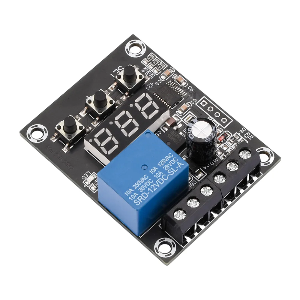
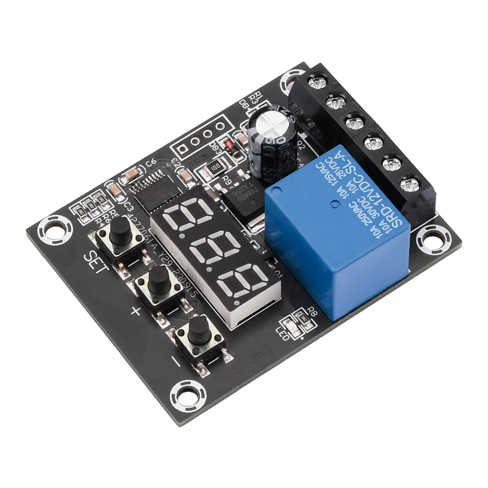
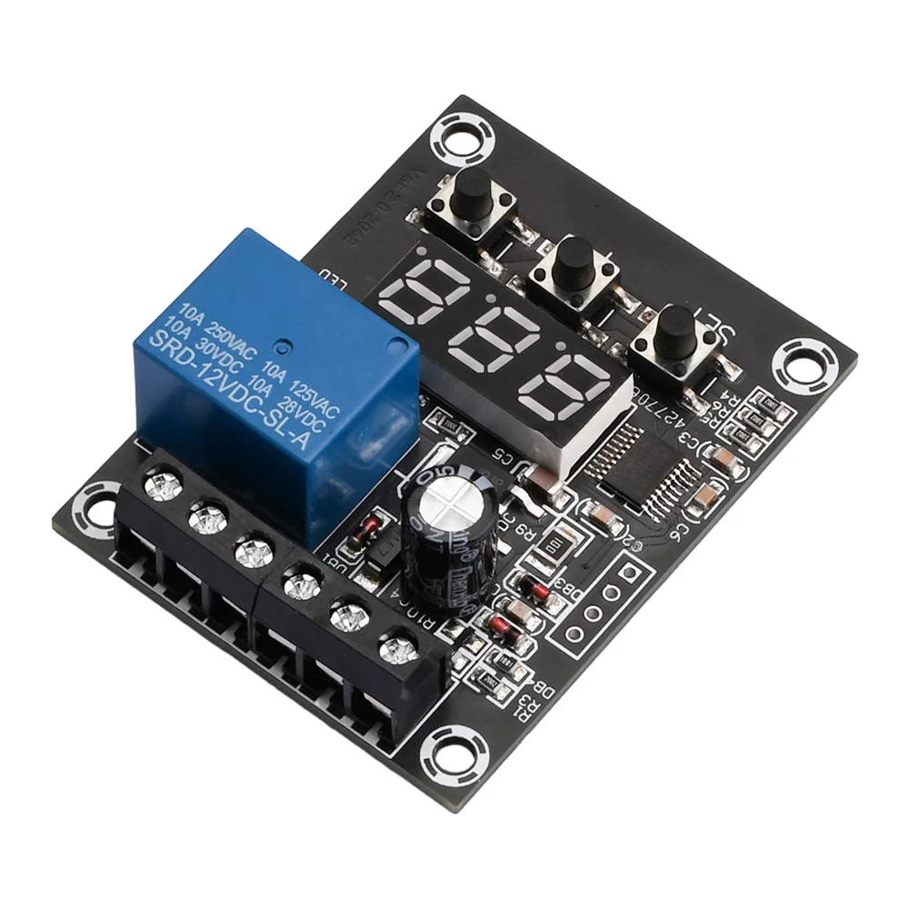
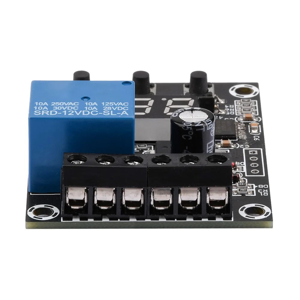
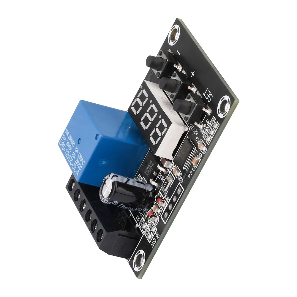
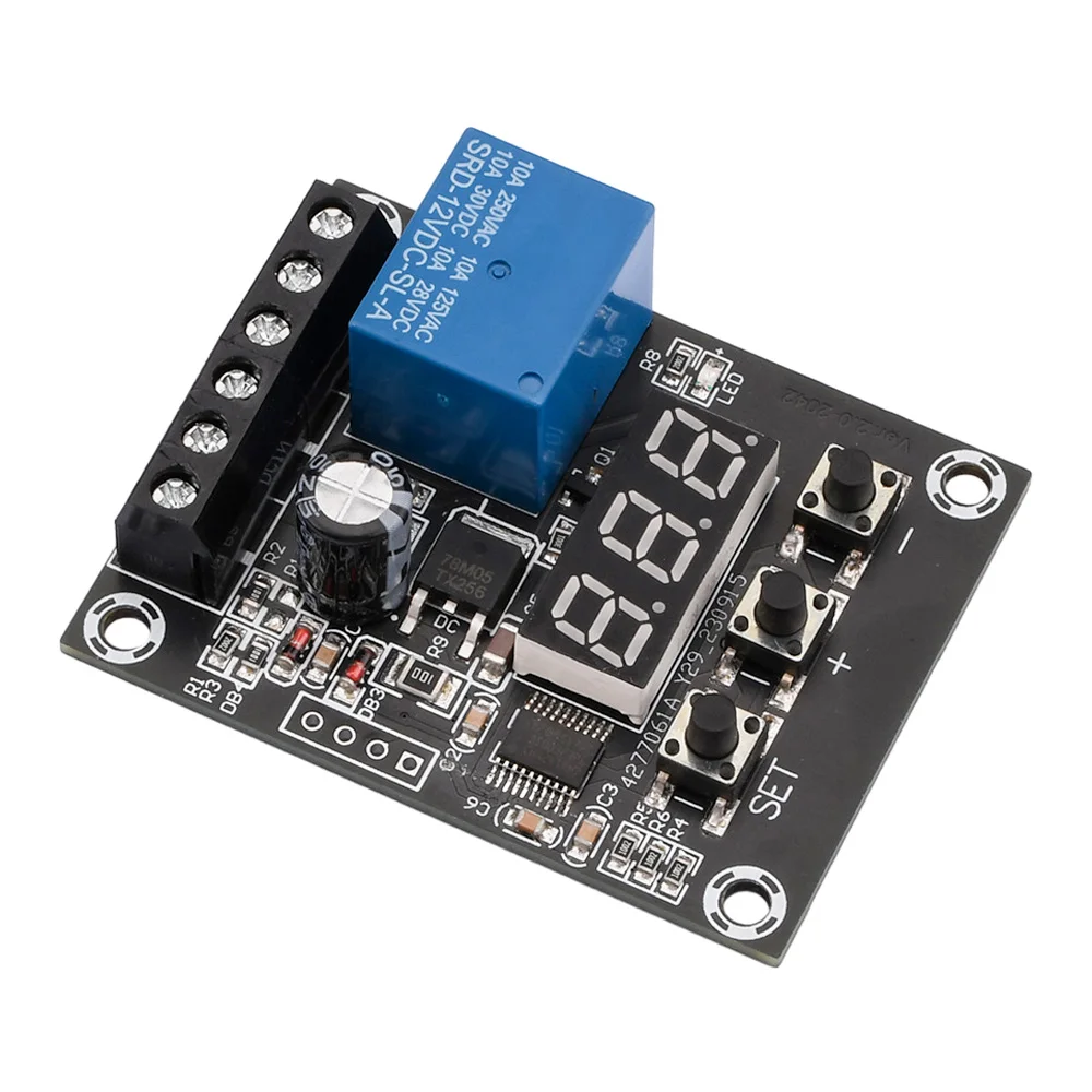
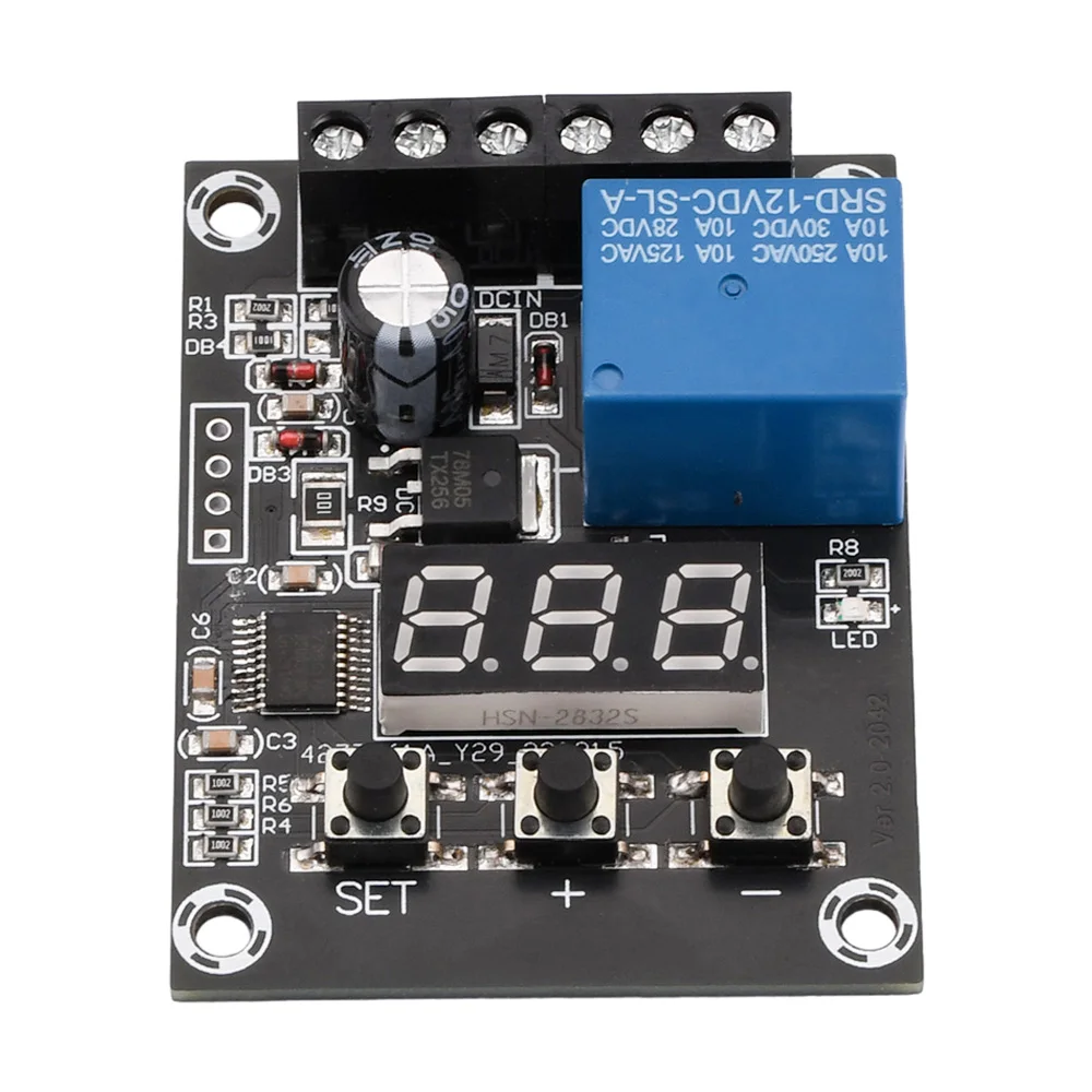
DC 9V 12V 24V Digital Voltage Control Relay Module Relay Switch Control Board Module LED Voltmeter Charging Discharge Monitor
Description:
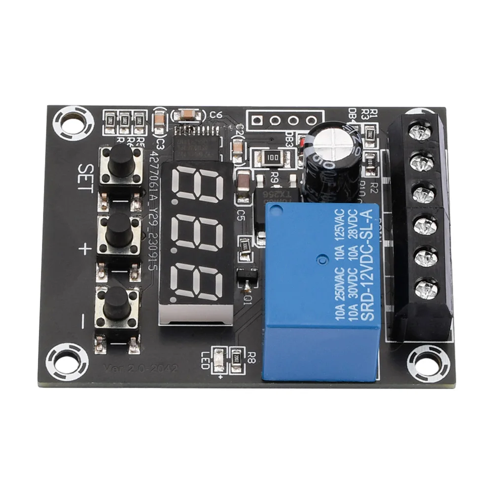
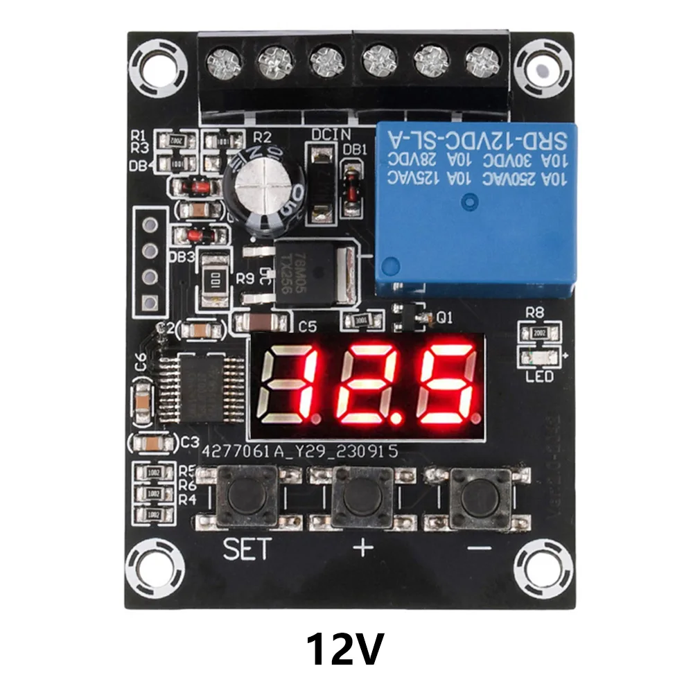
1.Powerful, with a detection range of DC 0-99.9V and a minimum of 0.1V adjustable;
2.Multiple protection functions, including charging protection, discharge protection, overvoltage protection, and undervoltage protection;
3.Fixed point pulse, stable performance;
4.Small compact , powerful function, and charge and discharge control;
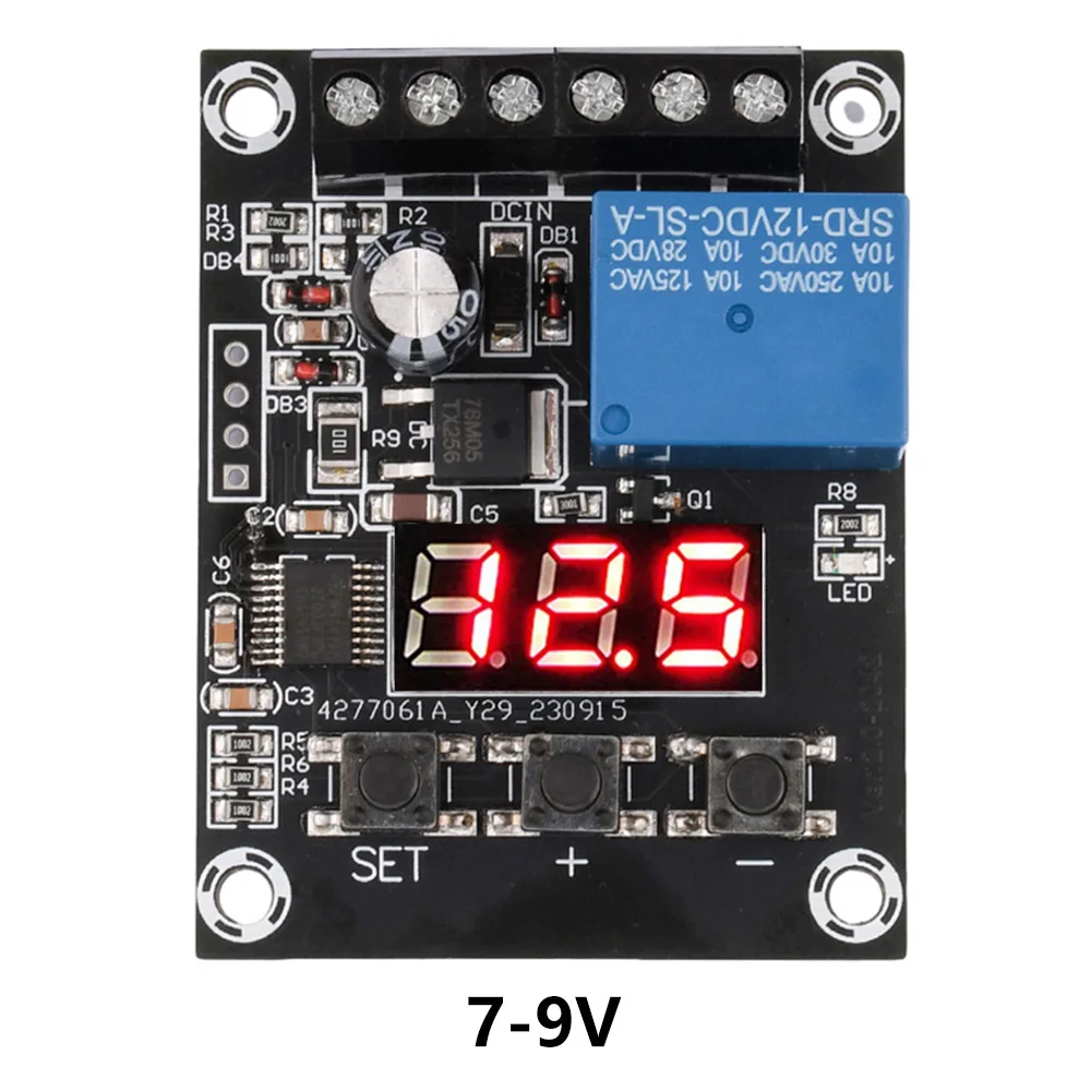
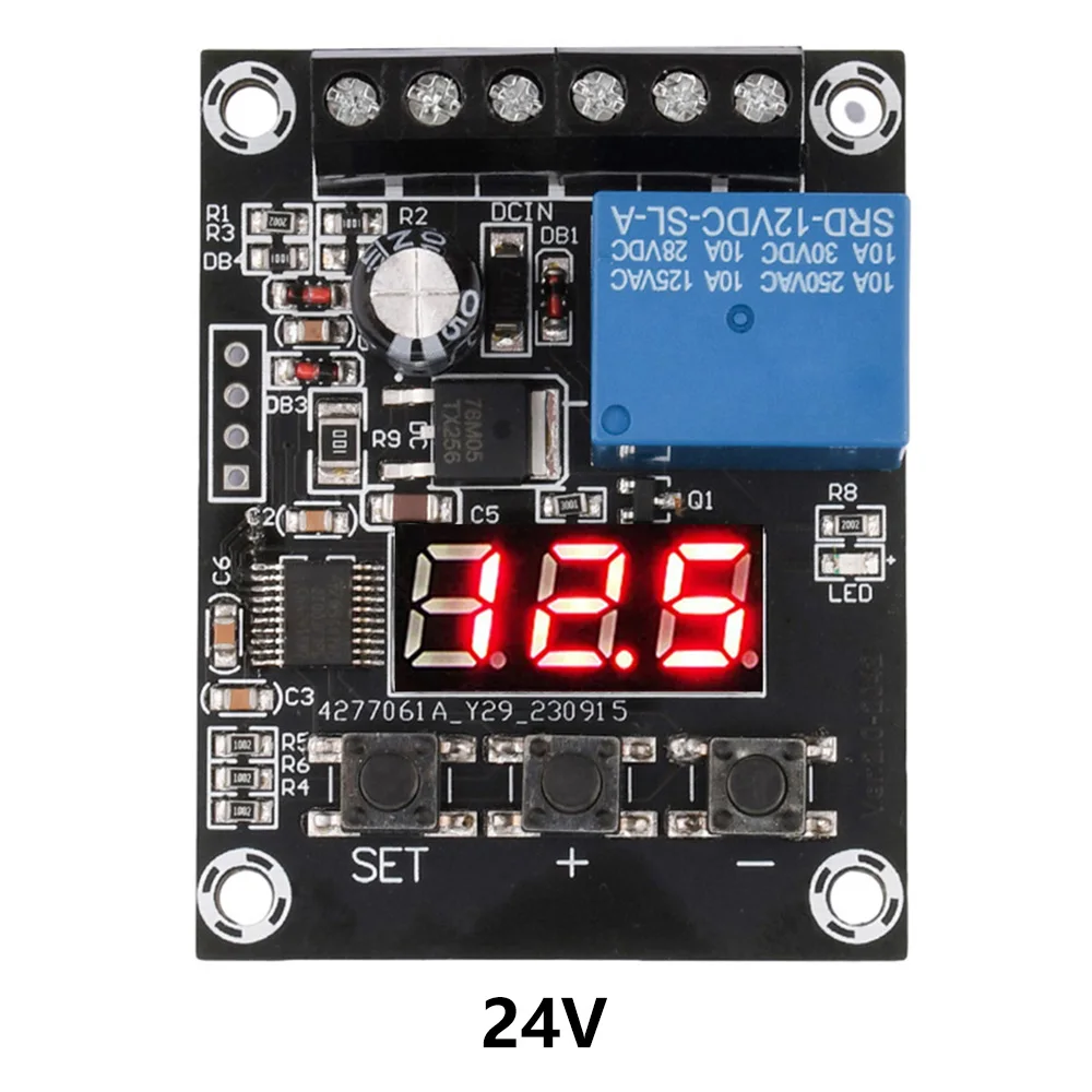
5.Multiple specifications are available, with options of 7-9V/12V/24V, which can be used with various voltage products.


DC7-9V 12V 24V Voltage Relay Module Upper Lower Limit Detection Control Switch Off ON Over Voltage Protection
$20.21
Sale price
$20.21
Regular price
$0.00
Description
SPECIFICATIONS
Brand Name: NONE
Certification: CE
Choice: yes
High-concerned chemical: none
Origin: Mainland China
Power Source: DC
Use: Protective
semi_Choice: yes
DC 9V 12V 24V Digital Voltage Control Relay Module Relay Switch Control Board Module LED Voltmeter Charging Discharge Monitor
Description:
1.Powerful, with a detection range of DC 0-99.9V and a minimum of 0.1V adjustable;
2.Multiple protection functions, including charging protection, discharge protection, overvoltage protection, and undervoltage protection;
3.Fixed point pulse, stable performance;
4.Small compact , powerful function, and charge and discharge control;
5.Multiple specifications are available, with options of 7-9V/12V/24V, which can be used with various voltage products.
Parameters:
Detection voltage range: 0-99.9V (minimum 0.1V adjustable)
Working voltage: DC 7-9V/12V/24V optional
Maximum current of relay contact: 12A (please leave some margin for use)
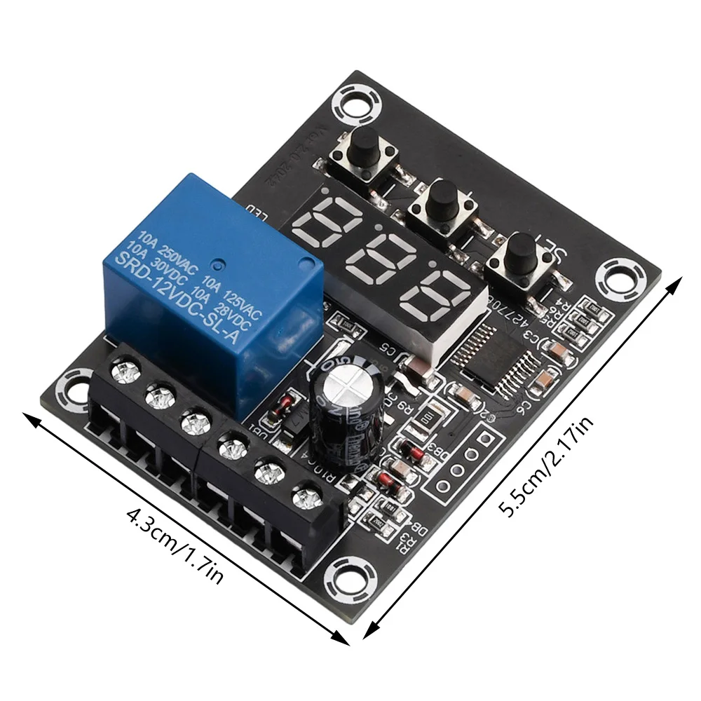
Product size: 56mm * 44mm
Introduction to operation:
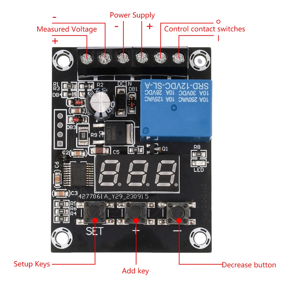
1. In a non set state, press the SET key briefly to cycle through the display: Work mode ->Lower limit voltage ->Upper limit voltage.
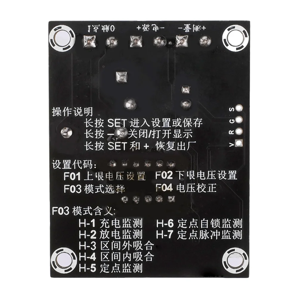
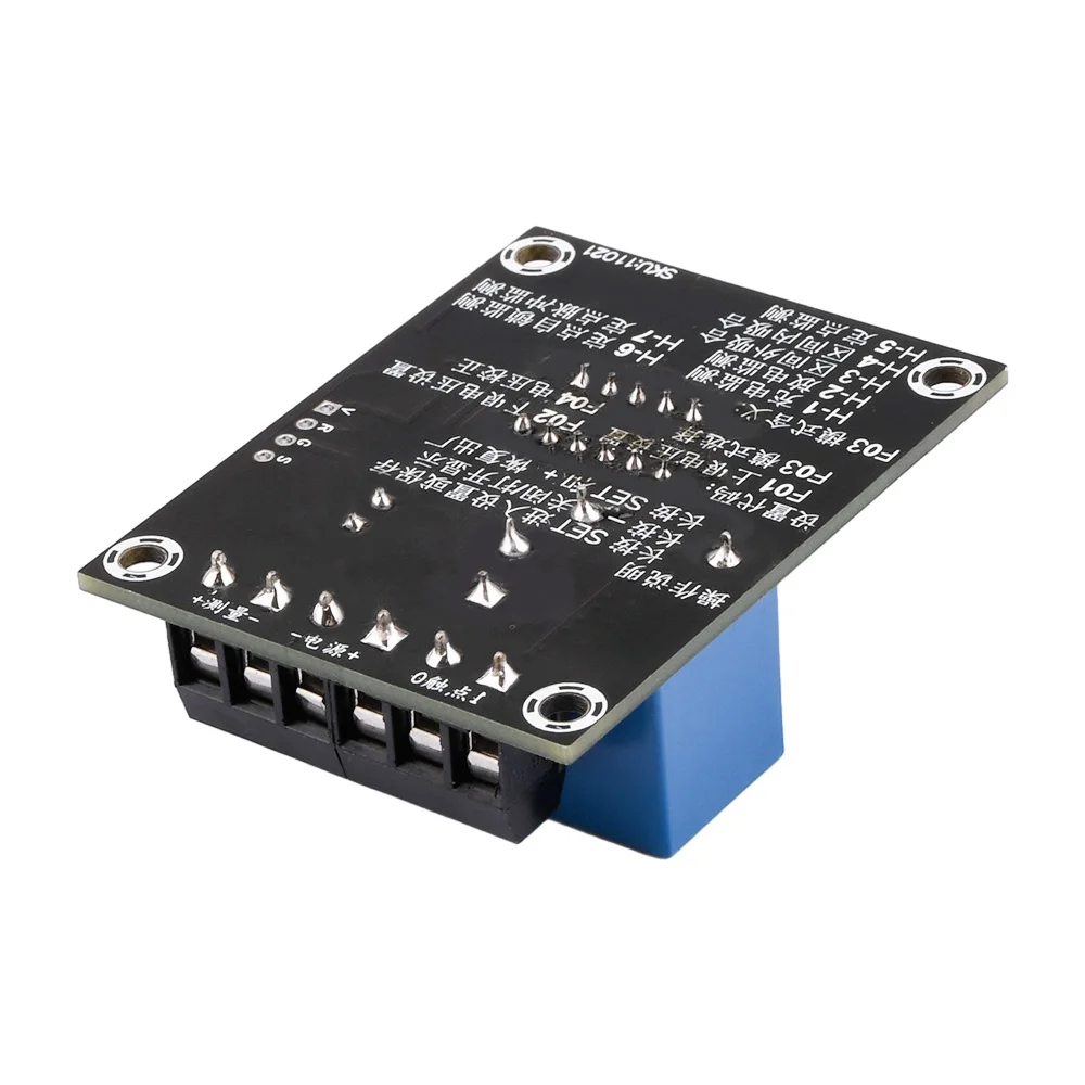
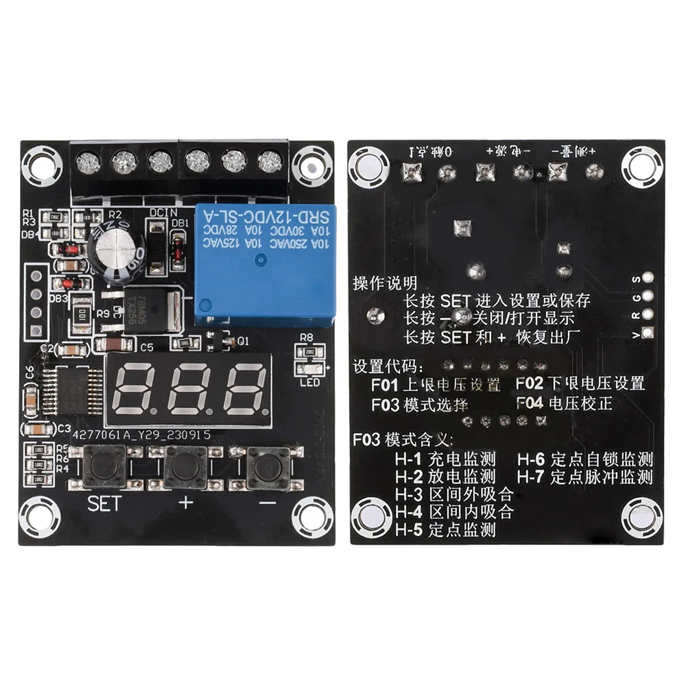
2. In a non setting state, press the Changan SET key for 2 seconds to enter the parameter setting state; The display shows F01, press the+- key to select the parameters to be set, such as F01 (upper limit voltage), F02 (lower limit voltage), F03 working mode, and F04 voltage calibration value.
3. After selecting the parameters to be set, briefly press the SET key to enter the parameter setting state. Press the+- key to adjust. When the lower limit voltage is greater than or equal to the upper limit voltage, the display will display an Err for 1 second, prompting the user. When the lower limit voltage is equal to the upper limit voltage, turn off the relay output function.
4.After setting the parameter values, briefly press the SET key to return to the parameter list.
5.After setting the parameters, press and hold SET for 2 seconds to exit and save the parameters.
6.In a non setting state, press and hold the SET and+keys for 2 seconds to restore the factory settings.
7.Long press - turn off or turn on Nixie tube to display energy-saving mode
Explanation of settings:
F03 working mode not set
Long press SET to select F03 working mode,+and - to select the desired function, then long press SET to save and exit
Please note that before setting this parameter, please set the upper and lower voltage as needed
H-1, charging monitoring: When the monitoring voltage is lower than the lower limit voltage, the relay is engaged, and when the voltage is higher than the upper limit voltage, it is disconnected
H-2, discharge monitoring: When the monitoring voltage is higher than the upper limit voltage, the relay is closed, and when the voltage is lower than the lower limit voltage, it is disconnected
When the monitoring voltage is between the upper limit voltage and the lower limit voltage, the relay disconnects when the H-3 interval is closed, and the relay in other states is closed when the monitoring voltage is between the upper limit voltage and the lower limit voltage
When the monitoring voltage is between the upper limit voltage and the lower limit voltage, the relay will pull in and disconnect in other states within the H-4 range
H-5 fixed point monitoring: When the monitoring voltage is higher than the lower limit voltage, the relay is engaged, and when the monitoring voltage is lower than the lower limit voltage, the relay is disconnected
H-6 fixed point self-locking monitoring: When the monitoring voltage is higher than the lower limit voltage, the relay will always remain engaged until manual intervention or power outage occurs
H-7 fixed-point pulse monitoring When monitoring each time equal to the lower limit voltage (± 0.1V), the relay outputs a jog signal
F04 calibration mode is not in the set state, long press the SET key to enter,+- select
The default is 0 error. If you need to adjust it as needed,
For example, if the actual input voltage is 12.5V and the module displays 12.4V, the error can be corrected here to 0.1V, which means 12.4+0.1=12.5
For example, if the actual input voltage is 12.5V and the module displays 12.6V, the error can be corrected here to -0.1V, which means 12.6-0.1=12.5
Package include:
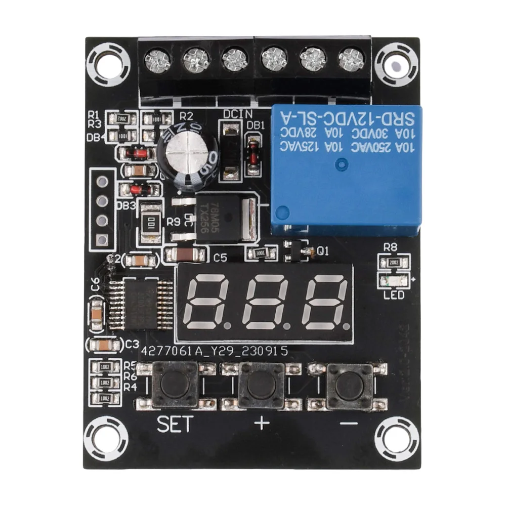
1pcs x Digital Voltage Control Relay Module Relay Switch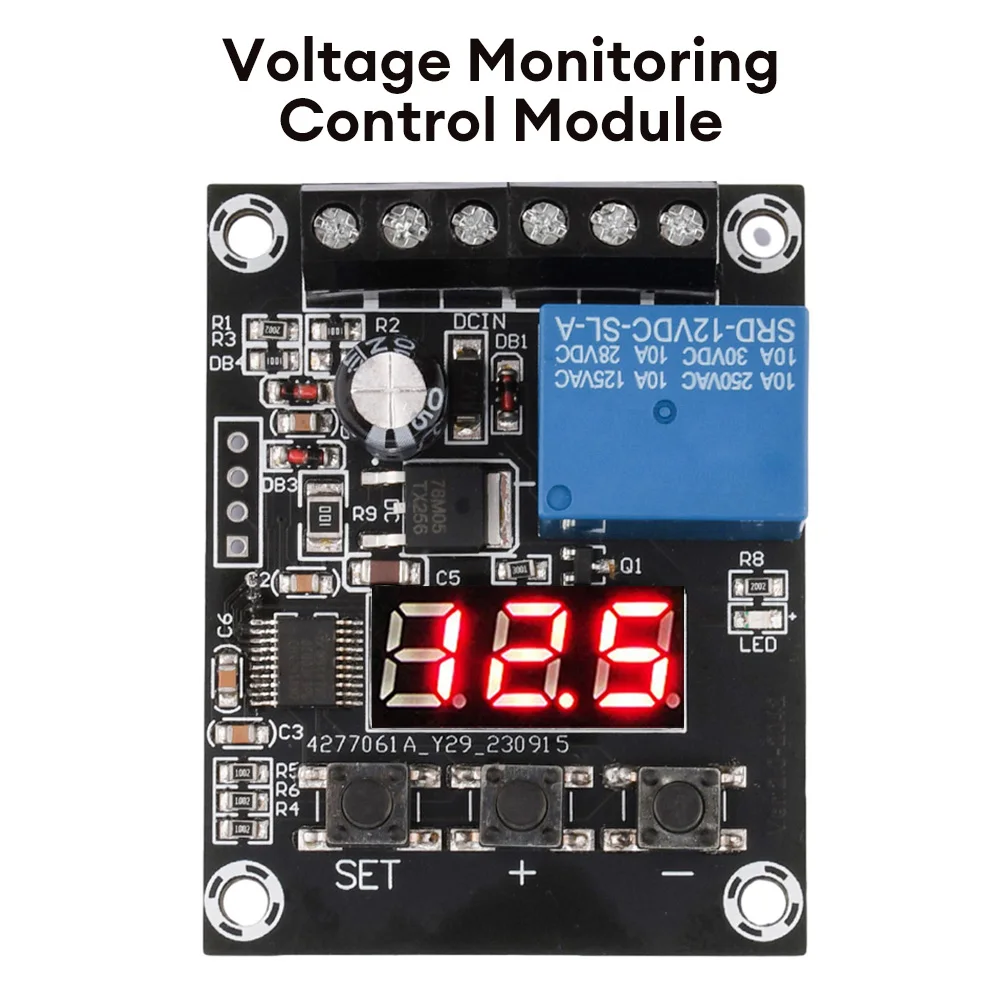
Free Shipping Over $199
- Standard Shipping: Standard Shipping (12–18 Business Days)
- Express Shipping: Expedited Shipping (5–9 Business Days)
- Free Shipping: Orders over $199 qualify automatically
- Tracking: Full tracking number provided for all orders
30-Day Return Policy
- Returns: 30-day hassle-free return window
- Condition: Items must be unused and in original packaging
- Refund: Full refund processed within 3-5 business days
Why Choose Us?
- Factory Direct: ISO/TS 16949 certified manufacturer
- Quality: 100% electrical continuity tested before shipment
- Experience: 15+ years in automotive connector industry
- Support: Professional technical support available

You may also like
Blog posts
Title
An excerpt of your blog post's content
Title
Date|Author
Subscribe to our emails
Be the first to know about new collections and special offers.