

RF-Nano Nano V3.0 Micro USB Board ATmega328P QFN32 5V 16M CH340 Integrate NRF24L01+2.4G Wireless For Arduino
MICRO
$32.49
Sale price
$32.49
Regular price
$0.00
Skip to product information


RF-Nano Nano V3.0 Micro USB Board ATmega328P QFN32 5V 16M CH340 Integrate NRF24L01+2.4G Wireless For Arduino
$32.49
Sale price
$32.49
Regular price
$0.00
Description
SPECIFICATIONS
Application: Computer
Brand Name: SZYTF
Choice: yes
Condition: New
Dissipation Power: N/A
Model Number: ATmega328P
Operating Temperature: N/A
Origin: Mainland China
Supply Voltage: N/A
Type: Module
Product description:
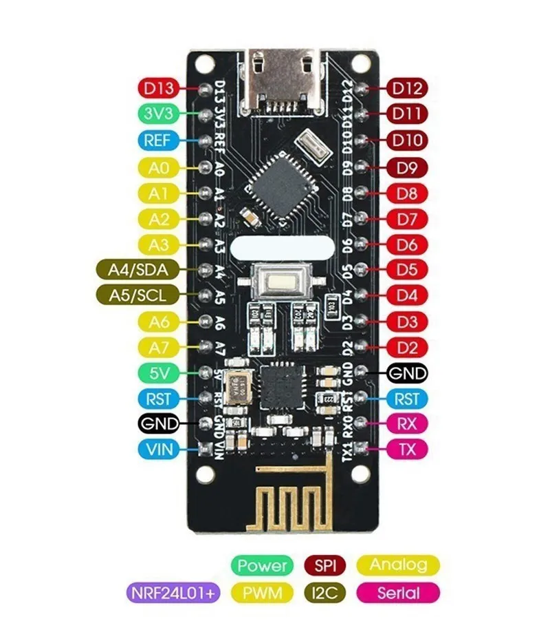
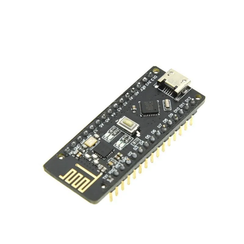
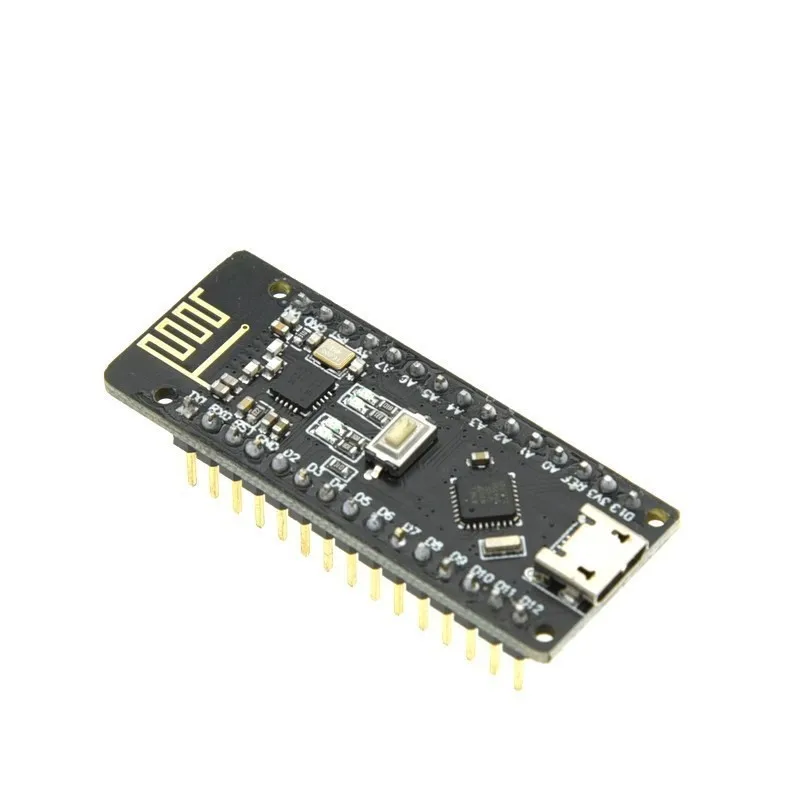
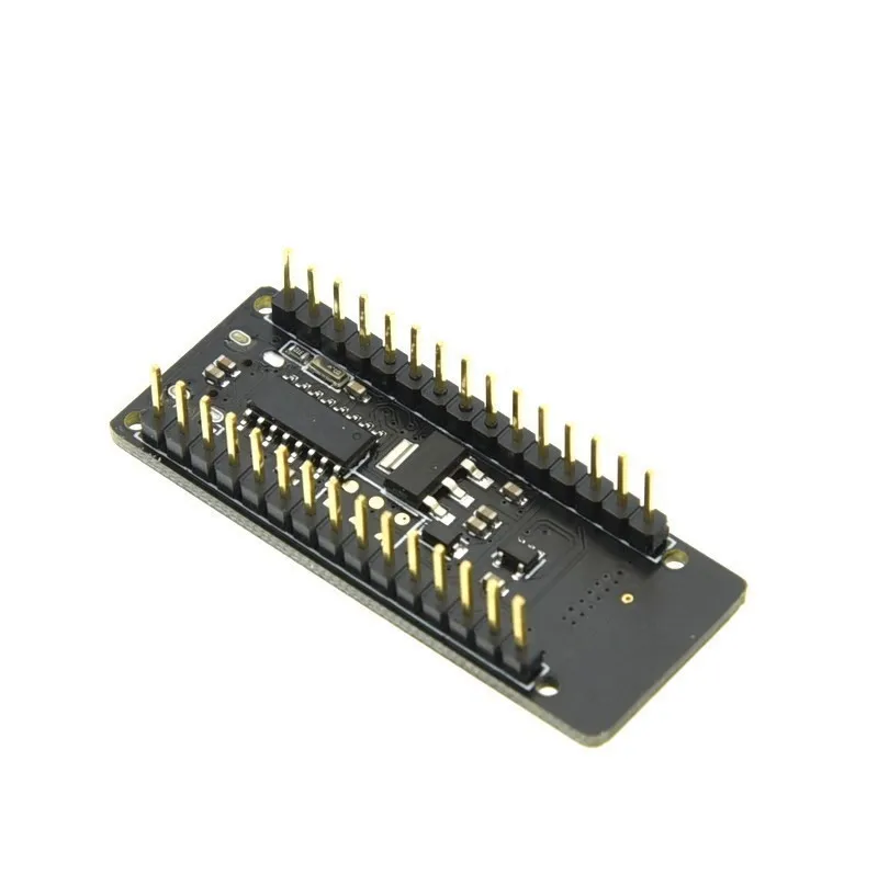
The NRF24LO1+ chip is integrated on the RF-NANO board, which makes it have unlimited transceiver functions, which is equivalent to combining an ordinary Nano board and an NRF24LO1 module into one, which is more convenient to use and small in size. The RF-NANO has exactly the same pins as the common Nano board, which is easy to transplant.
Processor introduction:
Processor: ATmega328
Working voltage: 5V Input voltage (recommended): 7-12V Input voltage (range): 6-20V
Digital IO pins: 14 (6 of which are used as PWM outputs) (D0~D13)
Analog input pins: 6 (A0~A5)
Io pin DC current: 40mA
Flash Memory: 32KB (2KB of which is used for bootloader)
SRAM: 2KB
EEPROM: 1KB (ATmega328)
USB to serial port chip: CH340
Working clock: 16 MHz
power supply:
RF-Nano power supply mode: Micro-USB interface power supply and external vin connected to 7~12v external DC power supply
Memory:
ATmega328 includes on-chip 32KB Flash, of which 2KB is used for Bootloader. Also 2KB SRAM and 1KB EEPROMo
input Output:
14 digital input and output ports: The working voltage is 5V, and the output and access limit current of each channel is 40mA. Each channel is configured with a 20-50K ohm internal pull-up resistor (not connected by default). In addition to this, some pins have specific functions.
Serial port signal Rx (No. o), TX (No. 1): provide the serial port receiving signal of TTL voltage level, and connect with the corresponding pin of FT232RI. External Interrupt (No. 2 and No. 3): Trigger the interrupt pin, which can be set as rising edge, falling edge or both.
Pulse width modulation PWM (3, 5, 6, 9, 10, 11): Provide 6 8-bit PWM outputs.
SPI ( 10(SS), 11(MOSI), 12(MISO), 13(SCK)): SPI communication interface.
LED (No. 13): Arduino is specially used to test the reserved interface of LED. When the output is high, the LED is turned on, otherwise, the LED is off when the output is low.
6 channels of analog input A0 to A5: each channel has a resolution of 10 bits (that is, the input has 1024 different values), the default input signal range is
0 to 5v, the upper limit of the input can be adjusted by AREF. In addition to this, some pins have specific functions.
TWI interface (SDAA4 and SCL A5): support communication interface (compatible with I2C bus).
AREF: The reference voltage of the analog input signal.
Reset: Reset the microcontroller chip when the signal is low.
Communication Interface:
Serial port: The built-in UART of ATmega328 can communicate with the outside through digital ports o (RX) and 1 (TX).
Free Shipping Over $199
- Standard Shipping: Standard Shipping (12–18 Business Days)
- Express Shipping: Expedited Shipping (5–9 Business Days)
- Free Shipping: Orders over $199 qualify automatically
- Tracking: Full tracking number provided for all orders
30-Day Return Policy
- Returns: 30-day hassle-free return window
- Condition: Items must be unused and in original packaging
- Refund: Full refund processed within 3-5 business days
Why Choose Us?
- Factory Direct: ISO/TS 16949 certified manufacturer
- Quality: 100% electrical continuity tested before shipment
- Experience: 15+ years in automotive connector industry
- Support: Professional technical support available

You may also like
Blog posts
Title
An excerpt of your blog post's content
Title
Date|Author
Subscribe to our emails
Be the first to know about new collections and special offers.